Blueprint symbols can represent a wide range of items, including walls, doors, windows, electrical and plumbing fixtures, structural elements, furniture, and more. They are usually standardized to ensure consistent communication across different projects and teams.
Table of Contents
What Are Blueprint Symbols?
Blueprint symbols are graphical representations used on architectural and engineering drawings to indicate various features, elements, and components of a building or structure. These symbols are used to convey information about the design, construction, and materials used in the building.
Examples of blueprint symbols include circles to represent electrical outlets, squares for light fixtures, lines with arrows for doors, and triangles for roof slopes. The symbols are usually accompanied by labels, notes, and dimensions to provide additional information and clarify the design intent.
Types Of Blueprint Symbols
1. Dimension Symbols:
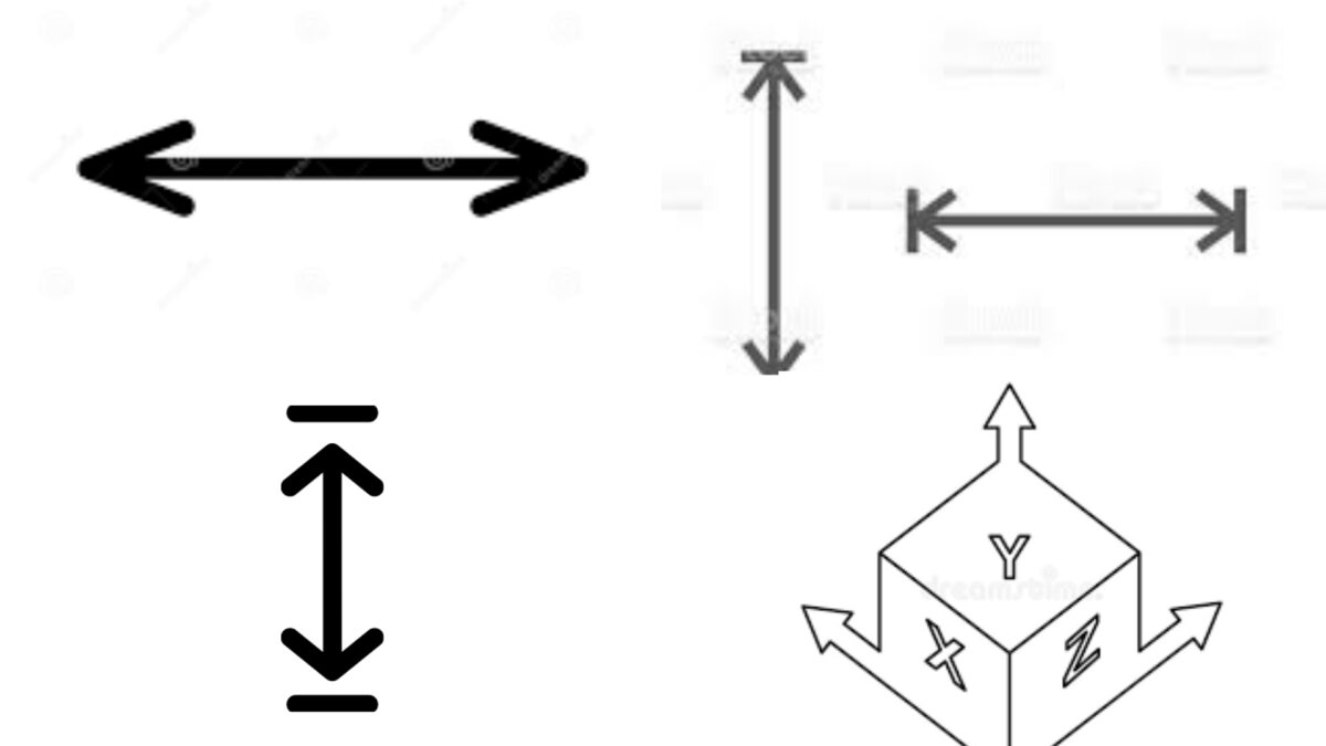
These symbols represent the size and location of features in a technical drawing. They include arrows, lines, and numbers that indicate length, width, height, and depth.
2. Geometric Symbols:
Geometric symbols represent shapes and angles in a technical drawing. They include circles, squares, triangles, and other shapes that indicate specific features or dimensions.
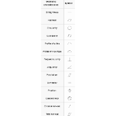
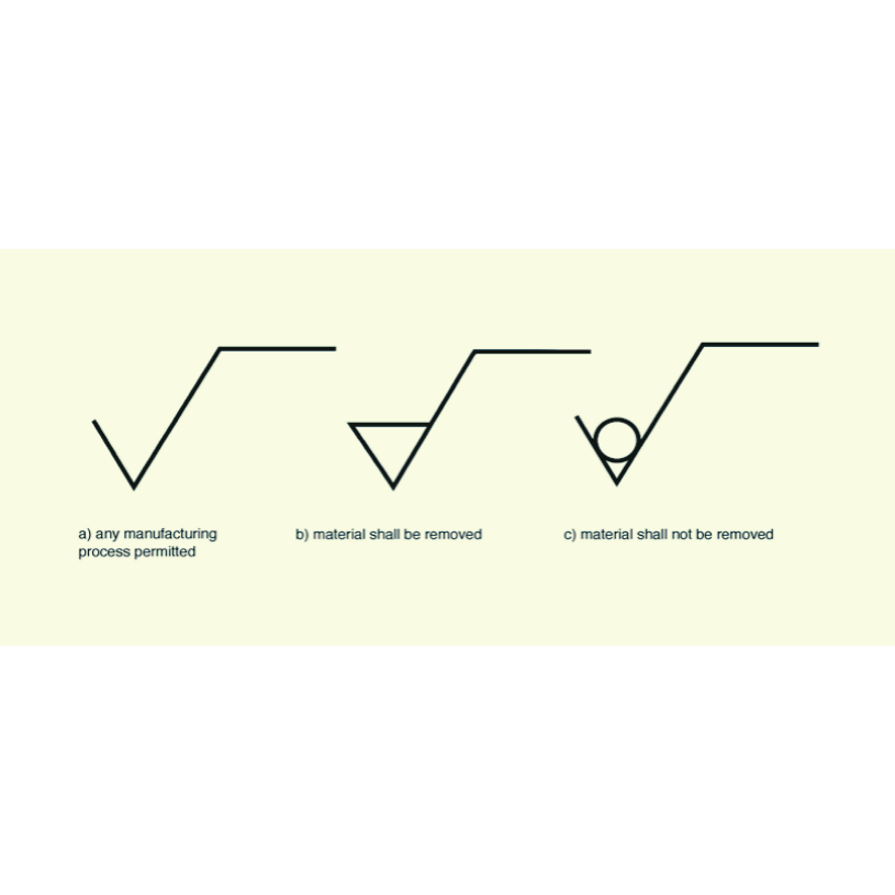
3. Surface Texture Symbols:
Surface texture symbols indicate the surface finish of a part or feature. They include lines, dots, and other patterns that indicate roughness, smoothness, or other surface properties.
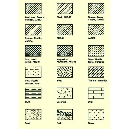
4. Material Symbols:
Material symbols represent the type of material used for a part or feature. They include letters, numbers, and other codes that indicate the specific material or alloy used.
5. Welding Symbols:
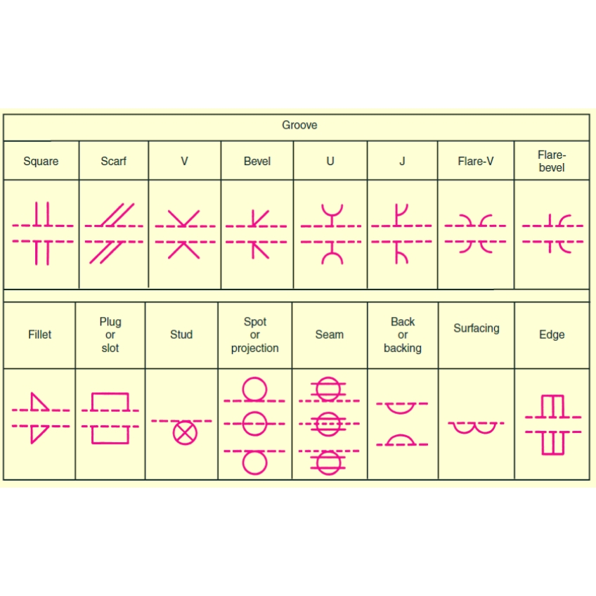
Welding symbols indicate the type of weld, its location, and other important details in a technical drawing. They include arrows, lines, and other shapes that indicate the type of weld and its orientation.
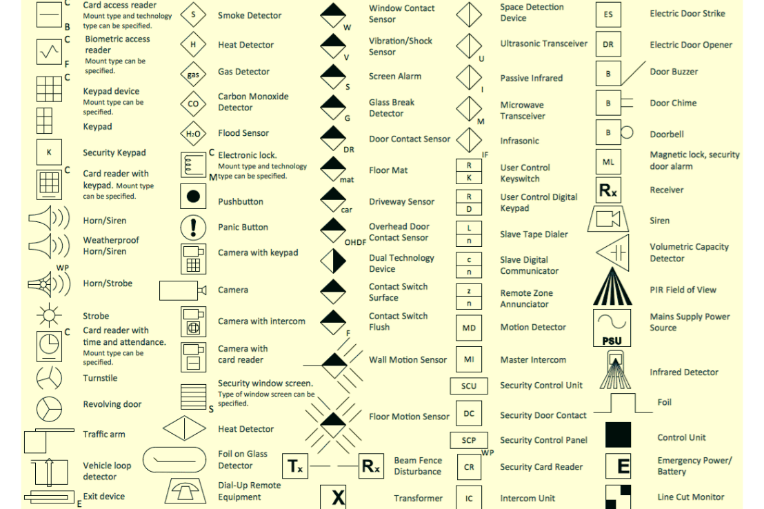
6. Electrical Symbols:
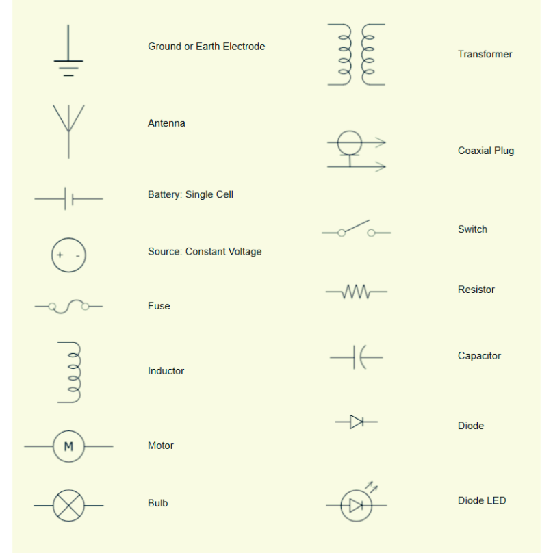
Electrical symbols represent the components and connections in an electrical system. They include lines, circles, and other shapes that indicate wires, resistors, capacitors, and other electrical components.
7. Plumbing Symbols:
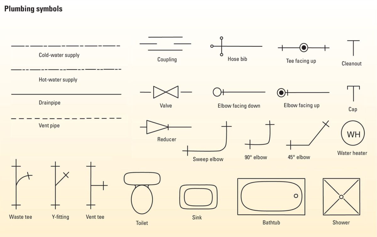
Plumbing symbols represent the components and connections in a plumbing system. They include lines, circles, and other shapes that indicate pipes, valves, and other plumbing components.
8. Piping Symbols:
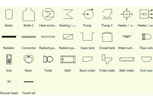
Piping symbols represent the components and connections in a piping system. They include lines, circles, and other shapes that indicate pipes, fittings, valves, and other piping components.
9. Architectural Symbols:
Architectural symbols represent various elements of a building or structure, including walls, doors, windows, stairs, and more. They include lines, circles, and other shapes that indicate dimensions, materials, and other important details.
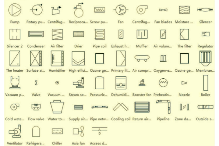
10. HVAC Symbols:
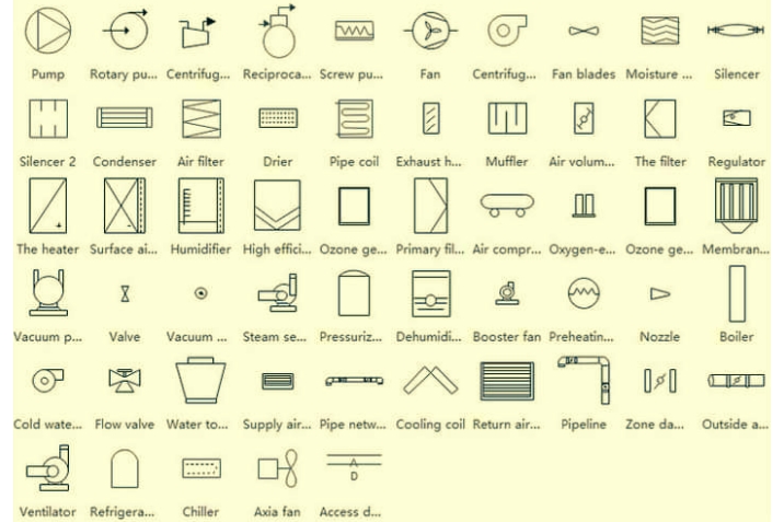
HVAC symbols represent components of heating, ventilation, and air conditioning systems. They include lines, circles, and other shapes that indicate ducts, vents, fans, and other HVAC components.
11. Fire Protection Symbols:
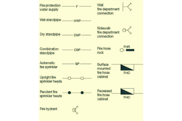
Fire protection symbols represent components of fire suppression and prevention systems. They include lines, circles, and other shapes that indicate fire alarms, sprinklers, fire extinguishers, and other fire protection equipment.
12. Instrumentation Symbols:
Instrumentation symbols represent components of industrial and process control systems. They include lines, circles, and other shapes that indicate sensors, controllers, transmitters, and other instrumentation components.
Conclusion
These are the most common types of blueprint symbols used in engineering drawings. Engineers and architectures must have knowledge of these blueprint symbols.