Table of Contents
Introduction of Dial Indicator?
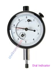
A dial indicator can be defined as a small gauge that can be used in various mechanical methods to measure specific deviations in mechanical parts. As for the various components of dial indicators, they consist of pinions, levers and gears.
See the below image of dial indicator.
However, it can be said that dial gauges are mostly used by operators to measure the deviation of straight planes. Also, the actual use of this gauge is as a comparator. A dial gauge therefore compares the deviation of a finished device to a standard device value and helps the operator to ensure that the finished device value is within the desired tolerance values.
How Does Dial Indicator Work?
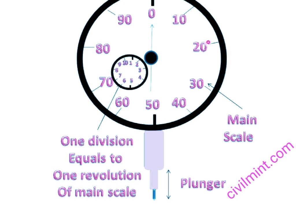
The component in front of the indicator, the piston, carries a rack on its back and slides on bearings to establish contact between the rack and pinion. The plunger is fixed inside the dial indicator so it can rotate around its axis. Therefore, to ensure the accuracy level of the measurement, the operator can use pins to limit it. Pins are assembled by the operator for guidance. Additionally, the plunger stays in place with the help of a coil spring. A pinion on the rack provides the connection between them, and a gear mounted on the same spindle rotates. Therefore, the gear and pinion mesh and the measurement increases. After that, the second gear meshed with the second gear, maybe this was the third gear. So the process ends here and the operator can get the scale factor.
A final magnification can be calculated by the following formula.
Final Magnification = Ng2/ Np3 × Ng1/Np2
g2 = Gear 2
g1 = Gear 1
p1 = Pinion 1
P2 = Pinion 2
Key Components of Dial Indicator
1. Dial Gauge and Needle
This is the most basic part of the dial gauge, as it is very important to have the dial gauge in contact with the measuring surface. Additionally, the movement of the hands and dial is incremented every minute within the mechanical component and measured on the display.
2. Piston
The piston is like a spring that moves perpendicular to the surface and can be measured by the operator. The operator therefore measures the movement of the piston as a result of the deviations present.
3. Faceted Pointer
This part of the dial gauge records all the data obtained with the help of linear area measurement. It’s also quite small compared to the dial embedded in the hands.
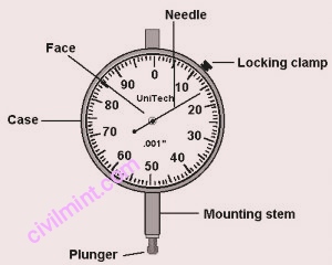
Check out the below image to know more about parts of dial indicator.
Advantages
- The dial gauge is very easy to use and the operating principle is so simple that even unskilled workers can use it. A uniform contact pressure can be obtained by using the dial gauge.
- Apart from that, the contact pressure is very low, so there is no stress on the mechanics.
- This device is immune to temperature changes and gauge wear.
- One of the most effective comparators in terms of mass production. A deviation of
- minutes can be recognized on the dial gauge.
- The accuracy of this instrument is very accurate and economical.
- The versatility of this instrument encourages users to measure deviation with this device.
- Mechanical parts can be measured very quickly.
- It is portable device.
Some Drawbacks
Operators can detect critical and noticeable errors due to piston and bearing wear.
There is backlash due to gears. Therefore, the dial indicator cannot be isolated from this issue. As such, game issues often cause operators to detect errors.
Vertical movement of the ram may cause the ram to move inward significantly, increasing the contact pressure. As a result, an error occurs within the device.
Uses
Engineers use dial indicators for workpiece alignment on a variety of machines including, but not limited to, mills, lathes, grinders, and EDMs.
Dial gauges are widely used in automobile disc brakes and are used to check lateral runout. Engineers reinstall disks when they fail. This can lead to bolt damage and uneven torque.
Even before production begins, the workshop uses dial gauges to calibrate the machines. This stage is the first stage of the manufacturing process used to ensure maximum accuracy of the output.
The boundary is narrow and it is difficult to measure the height difference of the boundary. This difference is the role of the dial gauge. You can easily measure such a slight height difference.
Deformation such as compression and tension is unavoidable in the manufacturing process. But it’s equally important to identify and eliminate them with dial indicators.
Dial gauges also have important applications in detecting surface position errors such as alignment, squareness and parallelism.
Accurate geometry is essential in the manufacturing process. For this reason, dial gauges are used to measure conicity, circularity, and ellipticity errors. When it comes to linear control, dial gauges are most preferred by engineers due to their accuracy. Especially in the manufacturing process, dial gauges play an important role in determining accuracy and consistency.