Shear Force and Bending Moment Diagram for a simply supported beam are as follows.
Table of Contents
Case 01. Simply supported beam with a point load.
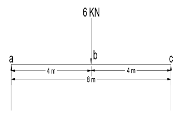
To find out Shear Force, first, we will calculate Ra and Rc.
Beam is simply supported ∑Ma = ∑Mc= 0.
Let us consider ∑Ma = 0.
6*4 – Rc*8 = 0 (Clockwise bending moment will be positive and Anti-Clockwise will be negative)
Rc = 24/8
Rc = 3
As we can see from the figure load is applied in the center, so both reactions will be the same.
Ra = Rc= 3 KN
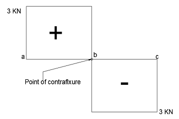
Now, we know the load on points a, b, and c. With the help of these points, we can draw the shear force diagram.
From the point, a to point b value of Shear Force will remain the same and then it will change downward on point b and then it will remain unchanged from point b to point c.
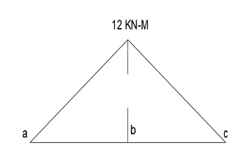
Bending Moment
In the case of simply supported beam bending moment will be maximum where shear force changes the sign and the bending moment at the supports will be zero.
Bending moment at point b, ∑Mb = Ra*4
∑Mb = 3*4
∑Mb = 12 KN-M
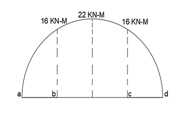
Case 02. Simply supported beam with uniformly distributed load (udl) & point load.

Beam is simply supported ∑Ma = ∑Md= 0.
As we can see the beam is symmetrical so both reaction Ra and Rd will be the same.
Let us consider ∑Ma = 0
4*2+2*4*4+4*6-Rd*8=0
Rd=Ra= 8 KN
Now we know the value of the load at points a, b, c, and d. With help of these loads, we can draw the Shear Force diagram.
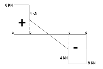
From the point, a to point b value of Shear Force will remain the same and then it will change downward from point b to c and then it will remain unchanged from point c to point d.
Due to udl value of shear force is decreasing from point b to c and it is linear this line follows the 1-degree equation.
Example of 1-degree equation = WL
Bending Moment:
The bending moment at the supports will be zero.
∑Ma = ∑Md = 0
The bending moment at points b and c will same due to the symmetry of the applied load.
∑Mb = ∑Mc = 8*2= 16 KN-M
Now we have to find Maximum Bending Moment
As we know at the midpoint of the span shear force is zero so the bending moment will be maximum at the midpoint.
∑Mmax = Ra*4-4*2-2*2*1/2
∑Mmax = 8*4-4*2-2*2*1/2
∑Mmax = 22 KN-M
The shape of the bending moment diagram will be parabolic because it follows a 2-degree equation.
Example of 1-degree equation = WL2
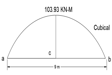
Case 03. Simply supported beam with uniformly varying load (uvl).
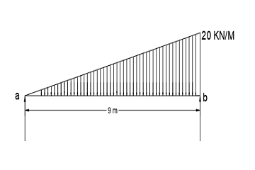
Beam is simply supported ∑Ma = ∑Mb= 0.
Let us consider ∑Mb= 0
Ra*9-1/2*9*20*9/3=0
Ra=30 KN
Ra+Rb= 90
Rb=60 KN
Due to the uniformly varying load (uvl) shape of the shear force diagram will be parabolic as you can see in the figure.
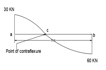
As we know beam is simply supported at both ends and it will not resist the bending moment at the supports that is why,
∑Ma = ∑Mb= 0
From the shear force diagram, we can analyze that at point c, the shear force is minimum and at this point bending moment will be maximum.
Now we will calculate bending moment at point c and we can call this moment ∑Mc max.
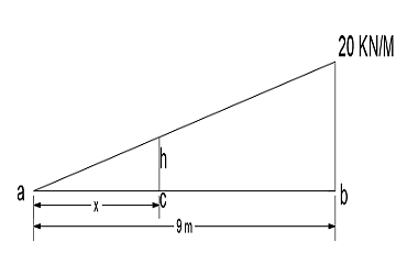
We don’t know the value of x and height at point x that we called h.
From the method of similar triangle
20/9 = h/x
h = 20/9 *x
From the below-given diagram at point, a shear force is zero.
Shear force at c = 30-1/2*x*h =0
30-1/2*x*20/9*x =0
By solving this equation we got
X =5.19 m
Now we will calculate the bending moment at point c and that will be the maximum bending moment.
∑Mc max. = 30*5.19-1/2*5.19*11.53*5.19/3
∑Mc max. = 103.93 KN-M
If you are facing any problem to calculate Shear Force and Bending Moment Diagram for a simply supported beam, you can comment below. I will try to assist you regarding Shear Force and Bending Moment Diagram for a simply supported beam.
Closing Words
Thanks for reading my article of SFD and BMD for simply supported beam. This is the easiest way to draw shear force diagram and bending moment diagram.
FAQ
By using the moment-area method or the method of sections to calculate the shear force and bending moment at various points along the length of the beam and then plotting them on a graph.
The bending moment is the force causing the beam to bend and support is the point where the beam is supported and not free to move.
SFD and BMD are graphical representations of the shear force and bending moment at various points along a beam’s length, used to analyze the behavior and strength of a beam.
By determining the loads and moments acting on the beam and then using those values to calculate the shear force and bending moment at various points along the length of the beam.
Read Also: