Table of Contents
Introduction
Vacuum brakes are a braking system used on trains and were introduced in the mid-1860s. A variant, the automatic vacuum braking system, became almost universal in British train equipment and in countries influenced by British practice.
Vacuum brakes were also briefly introduced in the United States, primarily on narrow-gauge railroads. Those limitations meant they were gradually superseded by British compressed air systems from the 1970s onwards. The vacuum braking system has been discontinued. They are not used on a large scale anywhere in the world except South Africa and have been largely replaced by air brakes.
What is Vacuum Brake?
Vacuum brake uses vacuum and atmospheric pressure to transfer force from the driver’s control to the service brakes, but to assist the driver in applying muscle force to hydraulic or mechanical components. Does not include systems that only use vacuum.

How it Works
In the below figure I have shown how vacuum brake works.
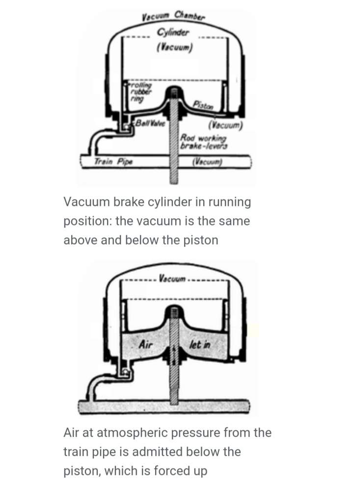
In its simplest form, an automatic vacuum brake consists of a continuous tube (train tube) that runs the length of the train. In normal operation, the tracks are kept in a partial vacuum and the brakes are released.
As air enters the draft tube, it acts at atmospheric pressure on a piston inside each vehicle’s cylinder. A vacuum is maintained on the other side of the piston so that a net force is applied. A mechanical linkage transfers this force to the brake shoe, which acts on the wheel tread.
Components of Vacuum Brake
1. Servo Cylinder:
A simple piston-cylinder arrangement with one side of the
piston rod connected to the brake shoe. In the brake release position, the piston is under vacuum on both sides. When the brakes are applied, one side of the piston is exposed to the atmosphere, applying a momentary braking force to the piston and pushing out the brake shoe.
2. Vacuum Reservoir:
When the engine is running, the vacuum in the power cylinder is created by the intake manifold, but when the engine is off, the vacuum reservoir is used to create the vacuum in the power cylinder.
3. Control unit:
The control unit is used to apply the brakes. It is also the arrangement of the piston and cylinder that uses the upper valve to connect the atmosphere to the power cylinder and the lower valve to connect the vacuum accumulator to the power cylinder. When the brake is applied, the upper valve is in an open state and the lower valve is in a closed state.
4. Non-Return Valve:
Non-return valve used to connect the power cylinder and the intake manifold, allowing only one-way air flow from the power cylinder to the intake manifold.
5. Master Cylinder:
The master cylinder is the same hydraulic brake used to operate the control unit.
Twin Pipe System in Vacuum Brake
The vacuum brake works in dual tube mode for faster application and release. The twin-tube vacuum system was standard on first-generation British Rail diesel duplex units, which replaced steam locomotive-hauled passenger trains in the 1960s. A second ‘high vacuum’ tube and associated reservoir and valve were used as a means of increasing brake release speed.
The vacuum extractors in these units were mechanically driven by the engine. The engine normally only idles when brake release is needed, so if you were using a traditional single-tube system, the release would be very slow. This problem did not occur on BR diesel locomotives. This was because the exhaust system was electric and could be activated to release the brakes at high speeds, regardless of engine speed.
Conclusion
Vacuum brakes nowadays only used in railway system. It does not use in modern vehicles. You can also check out my others articles on disc brake and drum brake.
Thanks for Reading!