Crankshaft position sensor is very important part of internal combustion engine. Internal combustion engines require a working crankshaft position sensor. Otherwise, the engine control unit will not receive accurate information about crankshaft position and speed. Crankshaft sensors are used in both petrol and diesel engines. This article explains how a bad crankshaft position sensor works, functions, and signs.
A Brief Explanation of Crankshaft Position Sensor
Basically it is an electronic device used in an internal combustion engine to monitor the position or rotational speed of the crankshaft. The Engine Control Unit (ECU) uses this data to control fuel injection or ignition timing and other engine parameters.
In older times the availability of electronic crank sensors, gasoline engines had to manually set the distributor to the timing marks.
A crankshaft position sensor can be used in conjunction with a similar camshaft position sensor to monitor the relationship between pistons and valves in an engine. This is especially important on engines with variable valve timing. This method is also used to “synchronize” the 4-stroke engine at start-up, so the management system knows when to inject fuel.
Also commonly used as the primary source for measuring engine speed in revolutions per minute.
How Does the Crankshaft Position Sensor Work?
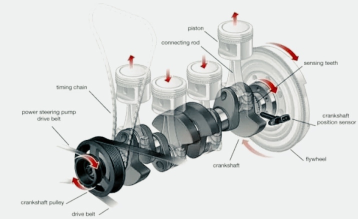
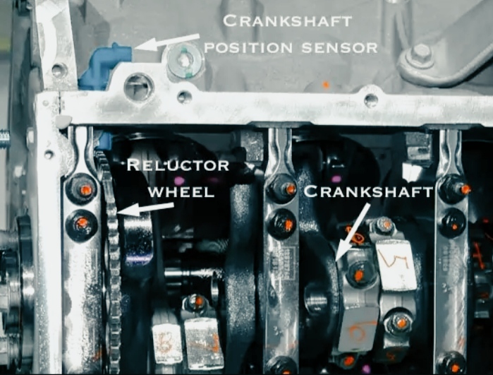
The crankshaft position sensor is positioned so that the teeth of the crankshaft-mounted reluctor ring pass near the tip of the sensor. The reluctor ring is missing one or more teeth to provide the engine computer (PCM) with a datum for crankshaft position.
As the crankshaft rotates, the sensor produces a pulsed voltage signal, each pulse corresponding to a tooth on the reluctor ring.
The PCM uses the signal from the crankshaft position sensor to determine when and on which cylinder to generate a spark. A signal from the crankshaft position is also used to monitor cylinder misfires.
If there is no signal from the sensor, there will be no spark and the injectors will not work. The two most common types are the magnetic sensor, which uses a pick-up coil to generate an AC voltage, and the Hall effect sensor, which generates a digital square wave signal like the one pictured above.
Modern cars use Hall effect sensors. The pickup coil sensor has a 2-pin connector. Hall sensors have a 3-pin connection (reference voltage, ground and signal).