Table of Contents
Introduction of Draft Tube
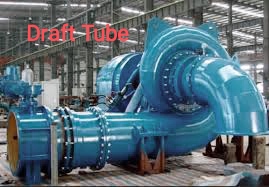
The draft tube is a connecting tube that gradually increases in area from the impeller outlet to the rear barrel. Draft tubes are one of the most important parts of water turbines used to convert water into energy.
For better visualization I have shown the image of draft tube.
Draft tube is used for various purposes as listed below:
- To convert dynamic pressure to static pressure.
- Larger area helps reduce cavitation effects.
- Converts the remaining kinetic energy of the water flowing out of the rotor outlet into pressure energy.
Function of Draft Tube
The main function of the draft tube is to slow down and increase the pressure of the fluid flowing from the impeller exit to the tail barrel.
Water enters the penstock and hits the turbine blades, reducing pressure. Tubes of gradually increasing cross-sectional area are used to slow down the water and increase the pressure before it enters the tail. A draft tube increases the water pressure to atmospheric pressure.
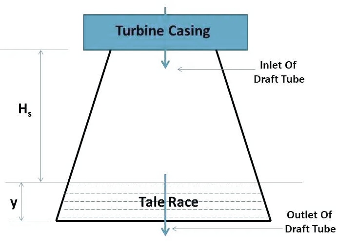
Let’s apply Bernoulli’s equation at section 1 – 1 and 2 – 2
[Pressure head + velocity head + elevation head] 1 – 1 = [pressure head + velocity head + elevation head] 2 – 2
Let us consider;
P1 = pressure of fluid at section 1-1 (inlet of draft tube)
V1 = velocity of fluid at section 1-1 (inlet of draft tube)
In the same way;
P2 = pressure of fluid at section 2-2 (outlet of draft tube)
V2 = velocity of fluid at section 2-2 (outlet of draft tube)
ρ = density of flowing fluid
g = gravitational force
hf = loss of head (energy) in draft tube
Hs = vertical height of draft tube above the tail race
y = distance of bottom of draft tube from tail race.
Pa = atmospheric pressure of fluid.
( P1 / ρg ) + ( V12 / 2g ) + ( Hs + y ) = ( P2 / ρg ) + ( V22 / 2g ) + ( 0 + hf )
( P1 / ρg ) = ( P2 / ρg ) – ( Hs + y ) + ( V22 / 2g ) – ( V12 / 2g ) + hf
Pressure head at section 2 – 2 is equal to atmospheric pressure head and distance y.
( P2 / ρg ) = ( Pa / ρg ) + y
( P1 / ρg ) = ( Pa / ρg ) + y – Hs – y + ( V22 / 2g ) – ( V12 / 2g ) + hf
( P1 / ρg ) = ( Pa / ρg ) – Hs + ( V22 / 2g ) – ( V12 / 2g ) + hf
Converting the equation for our requirement (i.e., in the middle of R.H.S taking “-” common)
( P1 / ρg ) = ( Pa / ρg ) – Hs – [ ( V12 / 2g ) – ( V22 / 2g ) – hf ]
In the above equation [ ( V12 / 2g ) – ( V22 / 2g ) – hf ] is called kinetic head.
Here [ ( V12 / 2g ) – ( V22 / 2g ) ] is the dynamic head.
From the above equation we can write
( P1 / ρg ) < ( Pa / ρg )
So P1 < Pa
The pressure head at the draft tube inlet or turbine outlet is less than atmospheric pressure. This increases the net head for turbines with draft tubes.
Types of Draft Tube
4 types of draft tube commonly used in industrial applications as given below.
- Simple elbow draft tube
- Elbow draft tube with varying cross section
- Moody spreading draft tube
- Conical diffuser draft tube
We will discuss about these 4 types of draft tube in detail.
1. Simple elbow draft tube
In this type of draft tube, the tube shape is an elbow and the cross-sectional area remains the same throughout the length of the draft tube. The inlet and outlet of the intake manifold are circular.
Used in low head locations. Used when the turbine is placed near the stern ring. The efficiency of this type of guide tube is approximately 60%.
2. Elbow draft tube with varying cross section
This type of draft tube is the modified version of a simple elbow draft tube. This type of intake manifold has a circular inlet and a rectangular outlet. The cross-sectional area changes from circular to rectangular from inlet to outlet.
The intake manifold outlet must be located below the stern ring.Commonly used on Kaplan turbines.The efficiency of this type of guide tube is approximately 70%.
3. Moody spreading draft tube
This type of intake manifold has one inlet and two outlets. The entrance and exit of the guide tube are circular.
A central fixed core divides both outlets. It reduces water turbulence.The efficiency of this type of guide tube is approximately 88%. Moody Spreader Tube is also known as HYDRA.
4. Conical diffuser draft tube
In this type of draft tube, the flow path is straight and bifurcated. The cross-sectional area varies from the beginning to the end of the intake manifold.
It is normally used for low specific speed vertical shaft Francis turbines. Cone angle is less than 100. A large cone angle causes cavitation.The efficiency of this type of guide tube is approximately 90%.
Clossing Words
In this article I have described about draft tubes, its function and types of draft tube. I tried to explain in a very simple way.
I hope you enjoyed this article. If you have any question, don’t hesitate to ask.
Thanks for reading my blog on draft tube.