Table of Contents
Orthographic Projection Definition
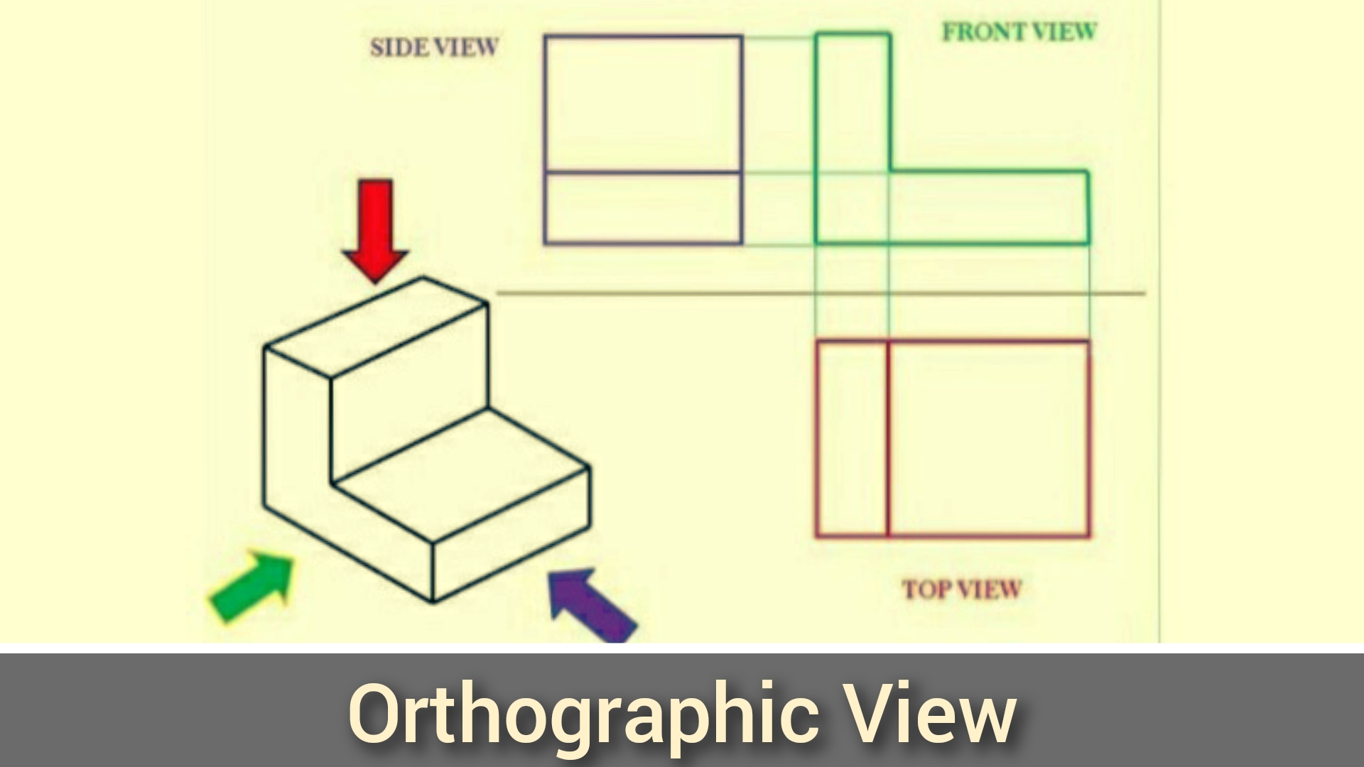
Orthographic projection is a technique used in engineering drawing, architecture, and design to represent a three-dimensional object in two dimensions.
What Is Orthographic Projection?
Orthographic projection, also known as orthogonal projection or analemma, is a technique for representing three-dimensional objects in two dimensions. It is a type of parallel projection in which all the projection lines are perpendicular to the projection plane, resulting in an affine transformation of every plane of the object onto the viewing surface. The opposite of orthographic projection is oblique projection, where the projection lines are not orthogonal to the projection plane.
In the context of multiview projection, the term “orthographic” refers to a technique where the principal axes or planes of the subject are also parallel with the projection plane to create primary views such as plans, elevations, and sections. If the principal planes or axes of an object in an orthographic projection are not parallel with the projection plane, the resulting depiction is called axonometric or auxiliary views, and sub-types include isometric, dimetric, and trimetric projections. Axonometric projection is a synonym for parallel projection.
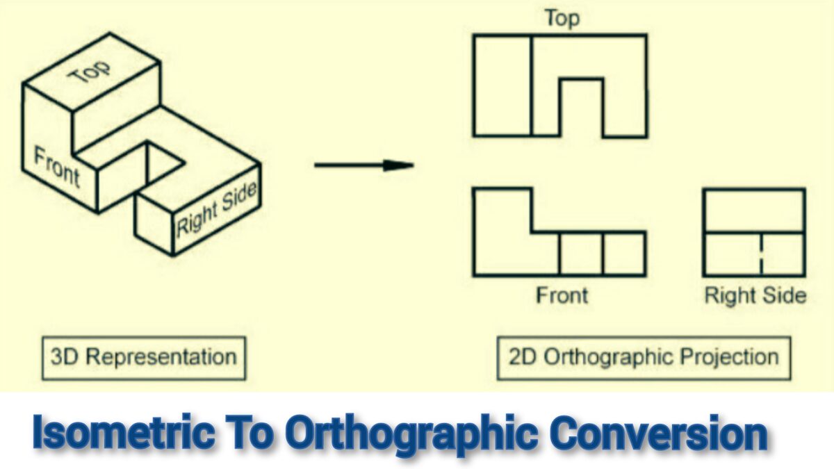
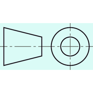
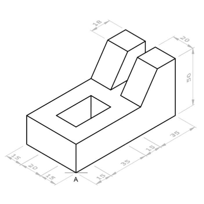
Isometric projection can easily be converted to orthographic projection. In the figure below, I have shown the isometric to orthographic transformation.
Orthographic Projection Examples
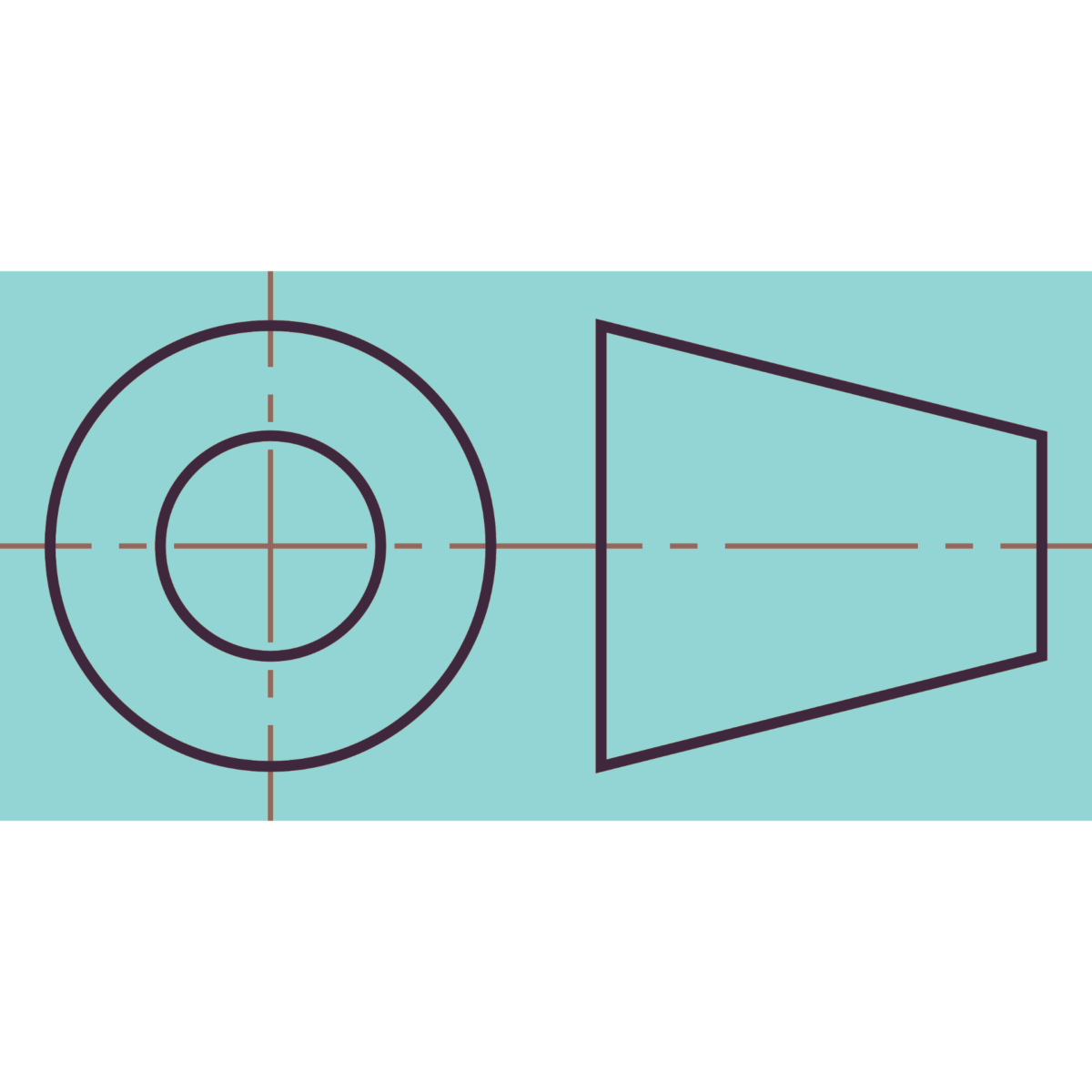
Various orthographic projections are shown below.
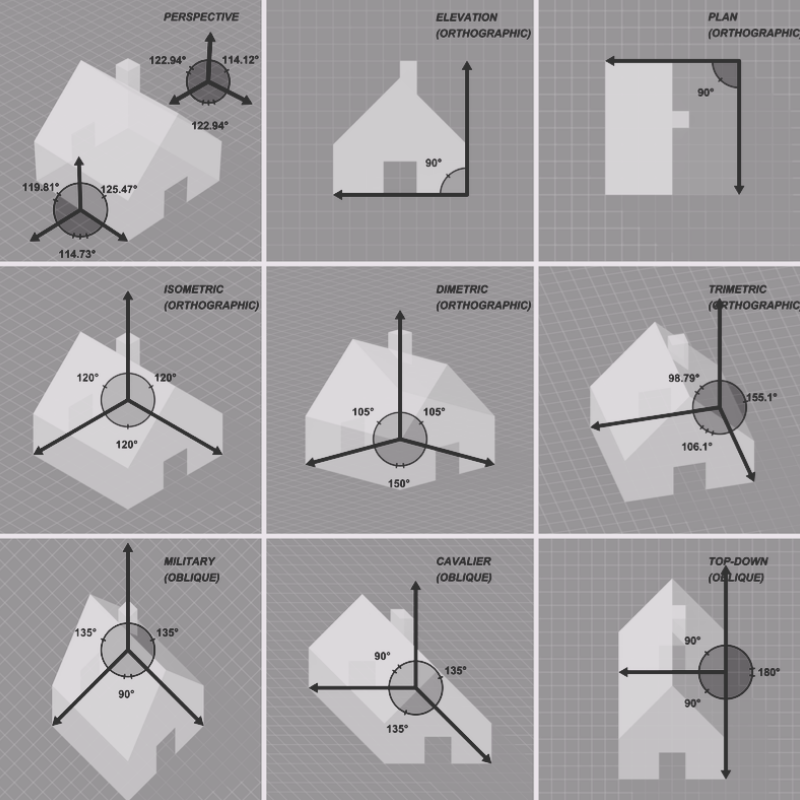
Types Of Orthographic Projection
Different types of orthographic projections are used in an engineering drawings. I have described various types of orthographic projections used in engineering drawings.
1. First-angle projection:
This is a method of projection in which the object is placed in the first quadrant of the view and projected onto a plane that is positioned between the object and the observer.
2. Third-angle projection:
This is a method of projection in which the object is placed in the third quadrant of the view and projected onto a plane that is positioned between the object and the observer.
3. Isometric projection:
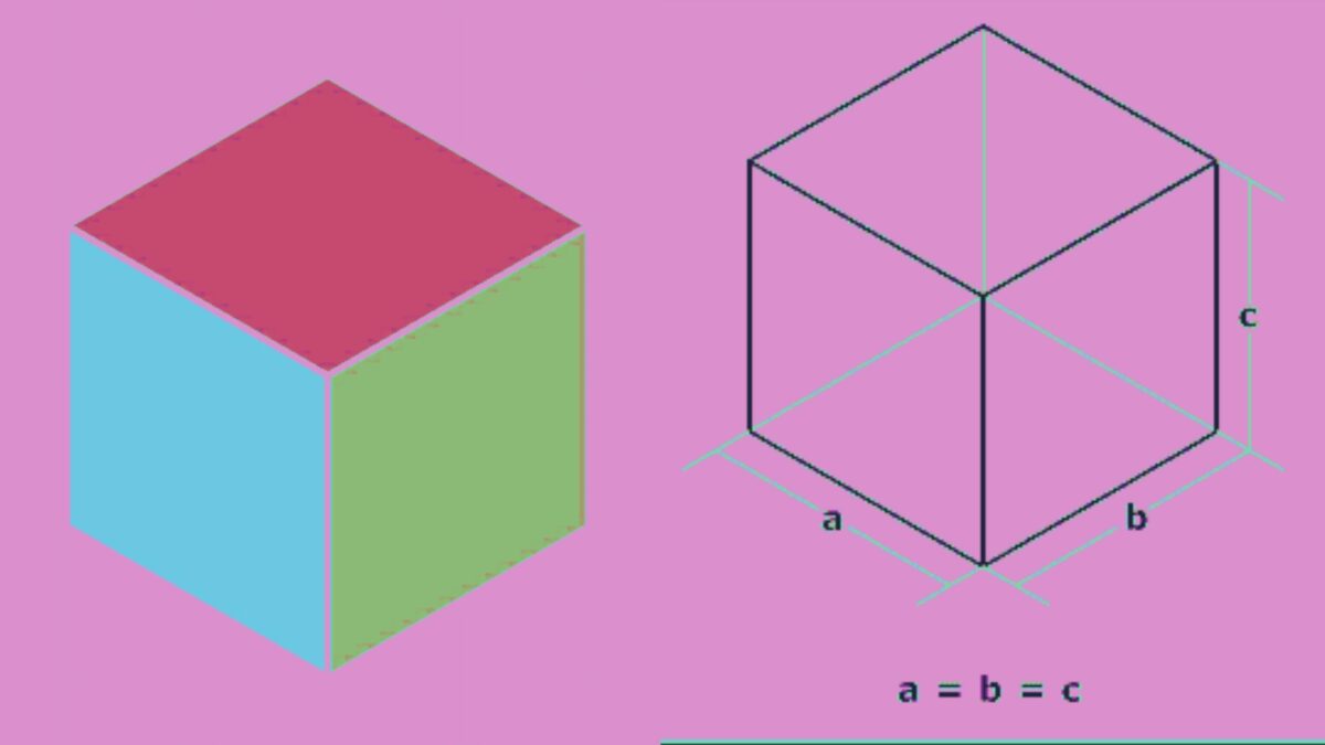
This is a method of projection that shows a three-dimensional object in a single view, with all three dimensions equally foreshortened.
4. Dimetric projection:
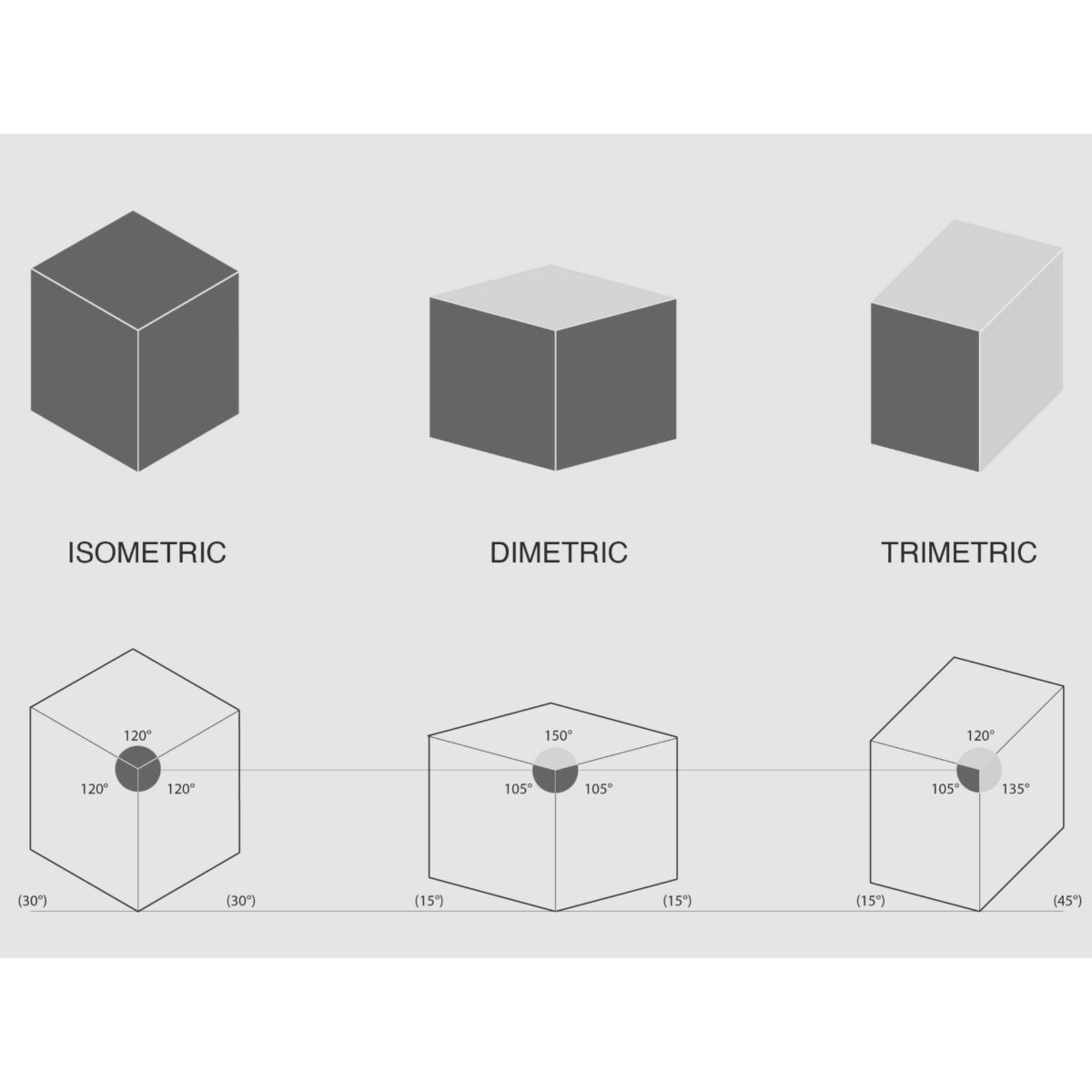
This is a method of projection that shows a three-dimensional object in a single view, with two of the three dimensions foreshortened.
5. Trimetric projection:
This is a method of projection that shows a three-dimensional object in a single view, with all three dimensions foreshortened but not equally.
6. Oblique projection:
This is a method of projection that shows a three-dimensional object in a single view, with one or more of the dimensions not foreshortened.
Principles Of Orthographic Projections
- Orthographic projection relies on three mutually perpendicular projection planes: the plan view, front elevation, and side elevation.
- Projection lines, which are perpendicular to the projection planes and connect corresponding points on the object, create the projected image.
- Orthographic projection maintains the true lengths and angles of an object’s features.
- Dashed hidden lines represent the edges of the object that are obscured from view.
- Visible lines represent the edges of the object that are visible in the current view.
- Auxiliary lines project features that are not parallel to the projection planes.
- Section views show the internal features of an object by cutting the object along a plane and showing the resulting cross-section.
- Dimensioning adds measurements to the projection, indicating the size and position of each feature.
- Orthographic projections are typically drawn to scale, meaning that the dimensions of the projection are proportional to the actual dimensions of the object.
- Consistency is crucial for accuracy in orthographic projection; the projection lines and planes must be consistent throughout the drawing.
Difference Between Isometric Projection And Orthographic Projection
I made a detailed table so that that you can easily understand the difference between isometric projection and orthographic projection.
| Isometric Projection | Orthographic Projection |
|---|---|
| Shows a 3D object with all three dimensions: height, width, and depth, at once. | Shows a 3D object in two dimensions, one view at a time. |
| The object appears at a 120-degree angle. | The object appears at a 90-degree angle. |
| Isometric projection drawings are often used for designs, blueprints, and presentations. | Orthographic projection drawings are often used for engineering, architecture, and manufacturing. |
| Has a skewed look that makes the object appear more realistic. | Shows the object in a more straightforward and simplified way. |
| Requires more skill and practice to draw accurately. | Easier to learn and draw accurately. |
| All lines are drawn at the same angle, making it easier to create. | Different views require different sets of lines and angles, making it more complex to create. |
| More commonly used in art and design. | More commonly used in technical fields such as engineering and architecture. |
| Often used to represent objects that have angled surfaces or curves. | Better for representing objects with flat surfaces or regular shapes. |
| Shows the object as a whole in a single drawing. | Shows each view of the object separately. |
| Difficult to determine the exact measurements of the object from the drawing alone. | Exact measurements of the object can be determined from the drawing. |
| Shows the object in a more visually appealing way. | Shows the object in a more functional way. |
| Can be used to show the object in motion. | Only shows the object at rest. |
| Does not require any auxiliary lines. | Auxiliary lines are required to show hidden or obscured details. |
| Gives a better sense of how the object would look in real life. | Does not provide a realistic sense of how the object would look. |
| Can be harder to read and understand for those unfamiliar with the technique. | Easier to read and understand for those unfamiliar with the technique. |
| Uses a single plane to show all three dimensions. | Uses multiple planes to show each dimension separately. |
| Can show the interior details of an object. | Only shows the exterior details of an object. |
| Can make the object appear larger than it actually is. | Gives an accurate representation of the object’s size. |
| The technique has been around since ancient times. | The technique was developed during the Renaissance period. |
| Can be used to create stylized or artistic drawings of objects. | Typically used for technical drawings and |
If I talk about in simple words;
- Isometric Projection: 3D
- Orthographic Projection: 2D
I hope you liked this article.
Thanks for reading.
Keep learning with us!