Table of Contents
Definition
Perspective projection is the representation of a 3D object on a two-dimensional drawing surface. The 2D surface can be paper or a computer screen.
Description
Perspective projection helps engineers and architecture visualize the perception of depth and distance. We will understand this concept using a camera. When we take a picture of an object, it converts the 3D object into a 2D object.
Perspective projection, in an engineering drawing, is used to show objects as they would appear in the real world when viewed from a specific perspective. Architectural and design engineers use perspective projection to create detailed and realistic representations of structures, machinery, and architectural designs.
By skillfully applying this technique, they can depict complex structures in an engaging way, which helps to understand the spatial relationships between different components.
In engineering drawing, perspective projection serves as a powerful tool for visualizing and conveying design intent, allowing clients, co-workers, and manufacturing teams to better understand the proposed project or product.
Objectives Of Perspective Projection
- Creating representations of actual construction for buildings and other objects.
- Developing models for various purposes.
- Illustrating drawings in pamphlets.
- Depicting different parts of assembly drawings.
- Representing the positions of moving objects.
- 3D designers construct these drawings to showcase real-life views.
Types Of Perspective Projection
There are 4 main types of perspective projection as discussed below:
1. One-point perspective projection:
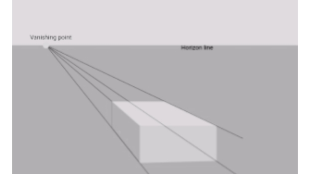
In one-point perspective projection, all lines and objects in the scene converge towards a single vanishing point on the horizon line, providing a sense of depth. For example, in the following image, the lines converge to a yellow point.
2. Two-point perspective projection:
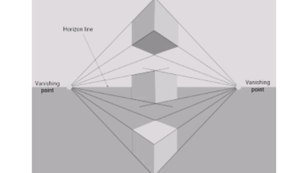
In two-point perspective projection, the receding lines converge to two vanishing points on the horizon line. For example, in the following image, the lines converge to two yellow points.
3. Three-point perspective projection:
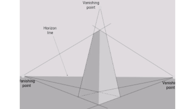
In three-point perspective projection, the receding lines converge to three vanishing points: two on the horizon line and one above or below it. For instance, in the following image, the lines converge to three yellow points.
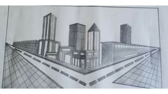
4. Zero-point perspective projection:
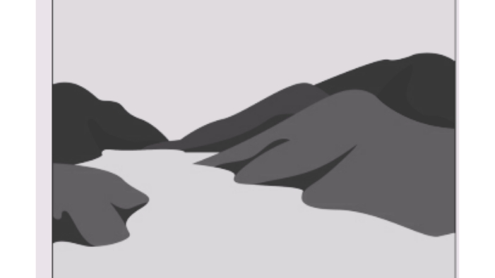
In this type of projection, there’s no convergence towards a vanishing point. The concept of vanishing points and a horizon line does not exist in zero-perspective images. For example, in the following image, there cannot be a convergence of lines towards a vanishing point.
Red Also: Orthographic Projection
Points To Remember While Creating Perspective Projection
- The drawing depicts the vertical axes as perpendicular lines.
- The horizontal lines in the drawing appear to converge at a specific point known as the Vanishing Point.
- The Vanishing Points are positioned on the horizontal lines within the System of Horizontal Lines.
- Horizontal lines within the horizontal plane are represented with their actual visible lengths.
- Lines situated in the picture plane appear shorter in length compared to their actual size.