Plinth beam is a very important building component. In this article we will know all the details related to plinth beam.
Table of Contents
What Is Plinth Beam?
A plinth beam is a reinforced concrete beam constructed between a wall and its foundation. M20 grade of concrete is used to construct plinth beam. Concrete grade should not be less than M20. It can be more than M20 as per project requirements.

The main purpose of a plinth beam is to provide support and strength to the walls of a building, to prevent expansion or expansion of cracks in the wall above the foundation when the foundation shrinks.
The plinth beam acts as a shield against potential damage and helps maintain the stability of the building. The plinth beam plays an important role in evenly distributing the load of the walls on the foundation.
Without plinth beams, the building’s walls may crack or bow over time, rendering the entire structure unstable. Therefore, it acts as a bridge between the foundation and the walls, ensuring that they work together harmoniously.
When constructing a building, the plinth beam is usually made of reinforced concrete, meaning it has steel rods inside to make it even stronger. This combination of concrete and steel makes the plinth beam very strong and reliable.
Plinth beam is an essential part of the building structure. Without plinth beams, the walls may be weak and may not be able to bear the weight of the entire building. It acts as a strong backbone for the building, ensuring that it remains tall and strong.
Design of Plinth Beam
1. Design Purpose
- Carries the load of the wall.
- Ties all the columns of that level.
- Resists lateral forces.
- Prevents differential settlement of buildings.
- Controls cracks in the masonry wall.
- Reduces effective length of columns to prevent buckling.
2. Dimension Requirements
- Width of Beam: Minimum 200 mm, not more than the width of supporting beams.
- Height of Beam: Not more than 1/4th of the Clearspan, not less than 200 mm.
- Width to Depth Ratio: More than 0.3.
- Span to Depth Ratio: In the range of 12 to 15.
3. Grade of Materials
- Grade of Concrete: Minimum M20 for reinforced concrete beams. M25 for buildings taller than 15 m in seismic zones III, IV, and V.
- Grade of Steel: Stirrups not less than Fe 415, Main Reinforcement of grade Fe 500 or Fe 550.
4. Reinforcement Detailing
- Top Reinforcement: Minimum two 12 mm diameter bars.
- Bottom Reinforcement: Minimum two 12 mm diameter bars.
- Transverse / Shear Reinforcement:
- Maximum spacing of shear reinforcement: 0.75 d for vertical stirrups and d for inclined stirrups at 45 degrees, with a maximum spacing of 300 mm.
- Minimum shear reinforcement: Asv/bSv > 0.75/0.87 Fy.
- Minimum diameter of shear reinforcement: Not less than 8 mm with U-link and 1350 hook at each end.
- First stirrup at a distance not more than 50 mm from the joint face.
- Spacing between stirrups not more than 150 mm.
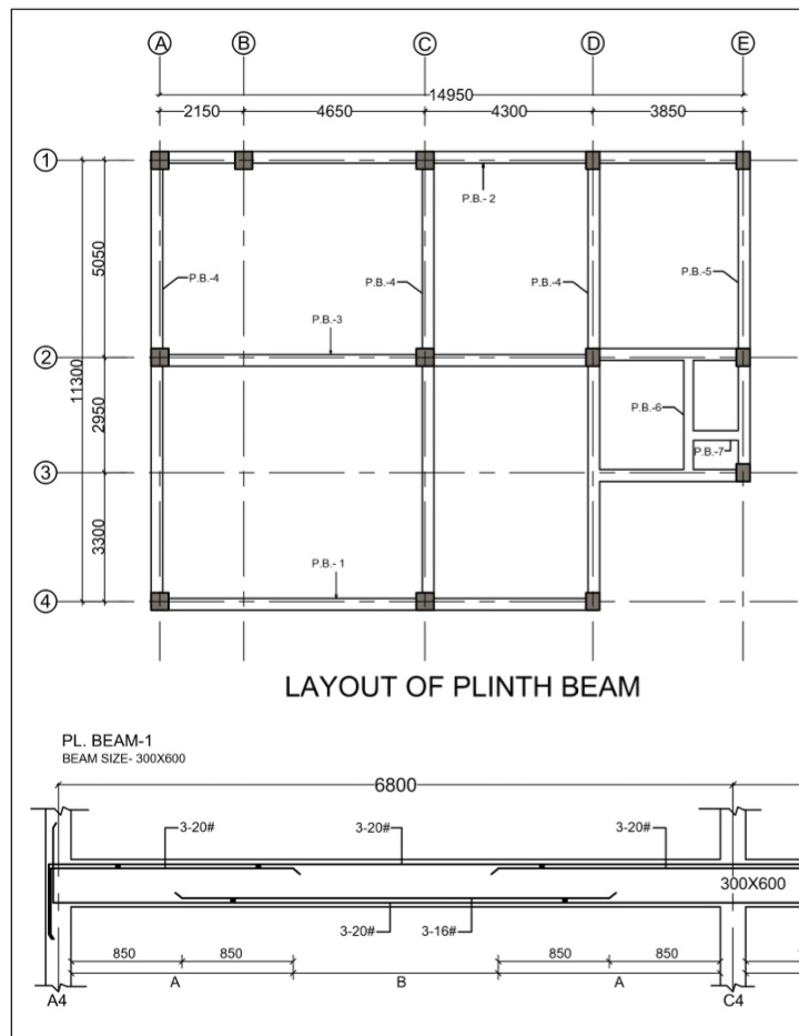
A typical reinforcement detail drawing for plinth beam is shown.
5. Minimum and Maximum Reinforcement
- Tension Reinforcement: Minimum area As/bd = 0.85/Fy, maximum area not more than 0.04 bD.
- Compression Reinforcement: Maximum area not more than 0.04 bD.
6. Lap Splices
- Lap length not provided within beam-column and beam-beam junctions.
- Not within 2d from the face of the column (d is the effective depth of the beam).
- Not within a quarter length of beam where flexural yielding may occur under earthquake effects.
- Not more than 50% of the area of a steel bar on either top or bottom face shall be lapped at any section.
- Lap length in the beam shall not be less than the development length of the largest longitudinal reinforcement bar in tension.
You Might Also Like: Grade Beam or Ground Beam