Table of Contents
Material Specifications
Individual piping class has been generally designed to cover a set of service operating within pressure-temperature consideration as per ASME B16.5/ B16.47A/ B16.34 or part of it.
Deviations of material from class specifications may occur due to specific
design conditions and/or availability. These deviations are permissible if they equal or better the individual class requirements and shall be subjected to approval on case-to-case basis.
Class Designator Code
The piping class designation shall generally be combination of two digits and two to four letters e.g. 1AC,2AC,3AC,1AS,2AS,3AS,1AAS,2AS,3AS etc. as follows:
First two numerals letter indicates ASME class rating, e.g.
1 – 150 Class
2 – 300 Class
3 – 600 Class
4 – 900 Class
The first alphabet indicates differences in the Fluid Services within the same class rating and material, e.g. A stands for Hydrocarbon, B stands for Water,
, C stands for Sea Water.
Last One Letter
C-Carbon Steel
S-Stainless Steel
AS-Alloy Steel
Some example of pipe
4AAS class means 900#, Alloy steel for Hydrocarbon service
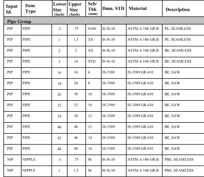
PIPES
MS Carbon steel pipe shall be made by open hearth, electric furnace or basic oxygen process only. The steel used shall be made with fine grain structure. The grade and wall thickness of various sizes of pipes shall be as per piping material specification for the applicable class.
Pipe dimensions shall be in accordance with ASME B 36.10 / IS 1239 /IS 3589 for carbon steel. All pipe threads shall conform to American Standard taper as per ASME B 1.20.1 NPT (unless otherwise specified).
For butt weld end, bevel shall be in accordance with ASME B16.25 as applicable.
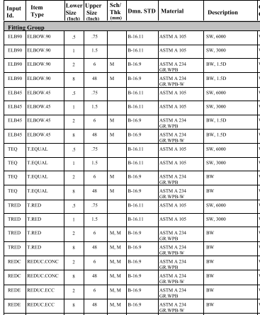
Fittings
Fully killed carbon steel shall be used in the manufacture of fittings. The fitting shall have carbon equivalent not exceeding 0.45, based on check analysis.
Threaded joints, if used, shall conform to American Standard taper as per ASME B1.20.1 NPT.
Dimensions of socket welded/screwed fittings shall conform to ASME B 16.11. Swage shall be as per BS 3799.
Dimensions of steel butt welded fittings shall be as per ASME B 16.9.
All welded fittings shall be 100% examined by radiography in accordance with the ASME Sec. V article 2.
Radiographic examination shall be carried out after final heat treatment.
Bore of socket welded fittings shall suit outside diameter (OD) of pipe and its
thickness.
Butt welding ends shall conform to ASME B 16.25 as applicable.
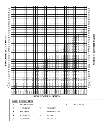
Integrally reinforced forged branch fittings such as Sockolet, Weldolet etc. shall be as per MSS-SP-97. Fittings not covered in ASME B16.9 and MSS-SP-97 shall conform to manufacturer’s standard.
Fittings thickness tolerances shall match pipe thickness tolerance.
BENDS:
Unless otherwise specified for process piping, elbow of radius R = 1.5 D shall only be used.
D = Specified Outside Diameter
Miters shall not be used
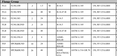
FLANGES
Pressure Temperature rating of flanges shall conform to ASME B16.5/ MSS SP-44/ ASME B16.47 Series A, as applicable.
Dimensions of flanges shall be in accordance with ASME B16.5/ MSS SP-44/ ASME B16.47 Series A, as applicable.
Neck of weld neck (WN) flanges shall suit pipe bore and thickness. Bore of socket welded (SW) flanges shall suit pipe O.D. and its thickness.
Threads for screwed flanges, if used, shall conform to American Standard taper as per ASME B 1.20.1 NPT.
Sizes for blind flanges shall be indicated by nominal pipe size.
Unless specified otherwise in Piping Material Specification the flange face finish shall be as per ASME B16.5.
Butt welding ends of WN flanges shall conform to ASME B 16.25.
Spectacle blind/spacer & blinds shall be in accordance with ASME B16.48/
manufacturer’s standard.
The finish of contact faces of pipe flanges & connecting end flanges of valves & fittings shall be governed by ASME B16.5 & following:
Roughness requirements (Finish: AARH standards per ASME B46.1):
a) Raised Face (RF): Serrated finish 125 to 250 μinRa.
b) Flat Face (FF): Serrated finish 125 to 250 μinRa.
c) Ring Type Joint (RTJ): Extra-smooth finish 63 μinRa max.
GASKETS
Spiral wound gaskets shall be used for ASME class 150# have inner and centering ring, unless otherwise specified in the individual piping classes.
Gasket shall be made of material that are suitable for the service applications and shall be capable of withstanding the pressure temperatures of subjected services.
Asbestos gaskets or asbestos filled gaskets shall not be used.
BOLTING & THREADS
Nuts for stud bolts shall be American Standard Hexagon Heavy Series and double chamfered.
Dimension and tolerances for stud bolts and nuts shall be as per ASME B18.2.1 and 18.2.2 with full threading to ASME B 1.1 Class 2A thread for bolts and Class 2B for nuts. Diameter and length of stud bolts shall be as per ASME B16.5/ASME B16.47 with full threading.
Threads for nuts shall be as per ASME B 1.1 as follows:
Nuts for stud bolts Dia ¼” to 1″ : UNC-2B
Nuts for stud bolts Dia 1⅛” to 3¼” : 8UN-2B
Threads for stud bolts shall be as per ASME B 1.1, as follows:
Stud bolts Dia ¼” to 1″ : UNC-2A
Stud bolts Dia 1⅛” to 3¼” : 8UN-2A
Threads for threaded pipe, fitting, flanges and valve shall be in accordance with B1.20.1 taper threads, unless specified otherwise.
Heads of jack screws shall be heavy hexagonal type. Jack screw end shall be rounded.
Stud bolts shall be fully threaded with two hexagonal nuts.
VALVES
Valve ends shall be as per valve data sheets for various piping class.
Sectionalizing valves, Block valves and other isolation valves installed
water piping shall be Gate valves with flanged ends.
All buried valves shall be provided with stem extension shall have Butt
as per relevant specification/ data sheet.
Flange dimensions and face finish of flanged end valves shall conform
this specification.
Butt welding ends of Butt Welded valves shall conform to ASME B 16.25
Face to face and end to end dimensions shall conform to applicable standards
Valves shall conform to following standards unless specified otherwise
material specification for various piping class.
Flanged/Socket Welded end valves (1½” and below) Design STD. for Process lines.
Gate Valves : API 602
Globe Valves : BS 1873 / ISO 15761
Check Valves : API 602/ ISO 15761
Ball Valve : API 6D / ISO 17292
Plug Valve : API 6D
Flanged/Butt Welded end valves (2″ and above)
Design STD. for Process Lines
Gate Valves : API 600/ ISO 10434
Globe Valves : BS 1873
Check Valves : API 6D / BS 1868
Ball Valve : API 6D
Plug Valve : API 6D
All manual operated valves shall be provided with wrench / hand wheel or gear operator as specified here in below.
Gate Valves:
For ANSI class 150 Hand wheel operated for size ≤ 10″ NB.
Gear operated for size ≥ 12″ NB.
Globe Valves:
For ANSI class 150 Hand wheel operated for all sizes
Ball Valves:
For ANSI class 150 Wrench operated for size ≤ 4″ NB.
Gear operated for size ≥ 6″ NB.
Actuated Valves:
Actuated valves shall be as per P & IDs. The actuator shall have provision for remote operation as per P & IDs. All Actuated valves shall have additional provision of hand wheel operation.
High point vents and low point drains required for the purpose of hydro test shall be of size 0.75″. These vents & drains shall consist of gate valves with end cap assembly.
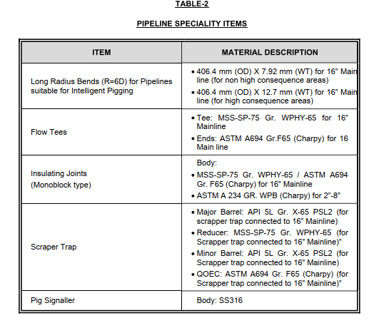
Piping specialty items shall be as per data sheets and specification.
Painting, color coding and wrapping shall be as per the Painting Specification
Pipeline Speciality Item
Example of pipe class table
Pipe Class-1BC 1-150#, B-Water, C-Carbon steel
Corrosion -1.5mm