Table of Contents
1.Preface:-
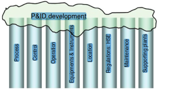
| Piping and Instrumentation Diagram (P&ID) is an important engineering document that shows the interconnection of process equipment and instrumentation to control the design system. P&IDs provide the primary schematic drawing used for detailed engineering. P&ID is a detailed drawing that consists of control devices, piping, process equipment, and instrumentation in the form of a diagram. This type of technical drawing is commonly used in practical fields such as engineering and process industry. P&ID drawings help industry professionals easily design, modify, and monitor a process from start to finish. P&ID consist all the process requirements during the design stage and construction of piping .there is some important notes which gives process information. (P&ID) development is always felt in the process industries. However, for a long time there no topic covered this topic. There are several reasons for this. One reason is the practical nature of this skill. A large number of topic written for working professionals are authored by university professors. The skill of P&ID development however is not pure theoretical knowledge. It is a combination of technical skills and other considerations like ease of operation, ease of maintenance, client preferences, and jurisdictional codes. On the other hand, the required technical skill is not exclusively in the territory of chemical engineers or instruments/control engineers or any other single engineering discipline. The set of skills for P&ID development comes from different engineering disciplines. Because of the above issues, the P&ID development skill is always considered as an “on the job learning” skill. The roadblocks of a topic on P&ID development are not only the vastness of the skill or the practical nature of it, but also some preventing beliefs. Some people claim that P&ID drawing is similar to a painting, which involves a bunch of creativity. Therefore “P&ID development” cannot be taught. However, the answer is in their question: even though painting needs a bunch of creativity it doesn’t prevent teachers/instructors from writing topic to explain the fundamentals of painting and also showing some of the creativities by other painters to spur the learner’s creativity. Some other people claim that P&ID development can be done only by following the company guidelines and such a topic cannot be taught as a general course. However, all the instructions in the company’s guidelines have underlying logic. This topic tries to explain these logical backgrounds. The goal of this topic is to provide information about the development of P&IDs for designers and personnel of process plants. When it comes to P&ID, there are three main group of knowledge may come to mind. They are: 1) The group of information on the technical “development” of P&IDs 2) The group of information that shows different elements on P&ID sheets 3) The group of information about how to draw already developed P&IDs (drafting P&IDs).A P&ID should first be developed (step 1), then drafted (step 3) based on the rules of P&ID appearance (step2). This topic doesn’t address how to “draw” a P&ID (group 3). There is plenty of software and plenty of training courses by the software companies that cover that topic. This Topic mainly focuses on the development of P&IDs and how to show different elements on P&IDs. The information in this topic will not only help in the development of P&IDs, but will also help in understanding the activities of process plants that are related to P&IDs. Chemical engineers will use this topic to learn how to design process plants based on selected and designed/ specified equipment or unit operations or process units. They will learn how to “tie” together different units to make sure the plant runs safely and produces the predetermined products with the highest level of operability. Chemical engineers and other engineers in process plants will use this topic so that they can read and interpret P&IDs deeply in order to maintain any piece of equipment in the plant and/or doing repair. There are several disciplines involved, including chemical engineering, mechanical, piping instrumentation and control, electrical engineering, and civil engineering disciplines. All disciplines involving a process plant should be familiar with P&IDs. All the items on a P&ID sheet went through two steps and several engineering disciplines. The depth of P&ID development could be defined as all activities to develop a P&ID but beyond the design. The design, in this context, means sizing or specifying a piece of an element such as a pipe, equipment, instrument, etc. There are different disciplines involved in the design of a process plant, including process engineering, piping and piping engineering, instrumentation and control engineering, mechanical engineering, and civil engineering. The former skill needs primarily knowledge of hydraulic calculations, pump/compressor sizing, vessel/tank sizing, PSV sizing, and heat exchanger sizing. At a higher level of sizing skill the chemical engineer should have the knowledge of designing different unit operation and unit processes. For example an engineer in the air purification industry may need to know about the design of different solid–gas separation units. Another engineer in the oil refining industry may need to know how to size a distillation tower. All of these sizing skills could have been learned during the acquisition of an engineering degree. As a P&ID gives a big picture of a plant, sometimes the mistakes in equipment sizing could be revealed when the equipment appears on the P&ID. Therefore, some of the concepts in this topic can be used to “roughly” check the accuracy of sizing of pipes and equipment. As was mentioned before, P&ID development skills are stretched over multiple disciplines. A P&ID sheet is the result of exhaustive work by different disciplines. Each item on a P&ID may be rooted in a deep concept of chemical engineering, instrumentation and control engineering, mechanical engineering, etc. |
At the beginning of P&ID development the items are added on P&IDs based on some calculations and sizing. However, when we progress further, the added items on P&IDs are not backed by quantitative documents but by qualitative, judgment‐type decisions.
1.2 What Is a P&ID?:-
A P&ID is the focal drawing in all process plants. P&IDs may be named differently by each company; however, P&ID is the most common. P&IDs can also be called engineering flow drawing (EFD) or mechanical flow diagram (MFD).
A process plant can be an oil refinery, a gas processing plant, a food processing plant, mineral‐processing plant, pulp‐and‐paper plant, pharmaceutical or petrochemical complexes, or water and wastewater treatment plants.
P&ID is a type of engineering drawing that describes all the process steps of a process plant. It basically is a process plant on a paper. A P&ID is a schematic diagram of pipes, process equipment, and control systems by a set of predecided symbols with no scale and no geographical
orientation. Equipment symbols are typically a side view of the real shape of the equipment, and if possible, are shown relative to their actual sizes.
1.3 P&ID Development Activity:-Input for P&ID
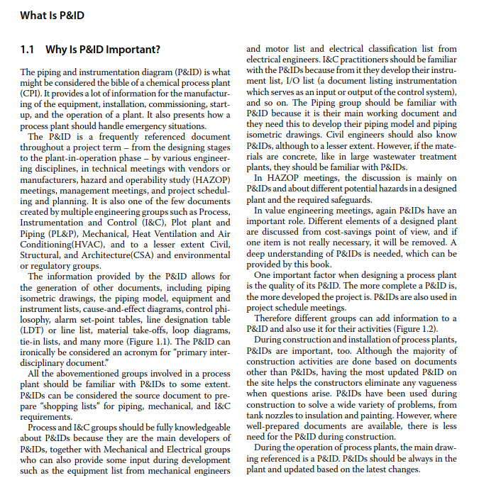
A P&ID is developed based on the information from process flow diagram (PFD), which is developed based on a block flow diagram (BFD). This is depicted in Figure 1.3.The BFD is the preliminary document in the development of a project and outlines the basics and general information of the project. The PFD is actually the expanded view of the BFD. It is the job of the designer to add further details to the PFD design before the final document – the P&ID – is developed. The BFD and PFD only show the main elements of the plant, whereas the P&ID shows more detailed elements. While BFD and PFD are normally considered internal documents of process engineers, P&ID is a cross‐discipline document.

Going through these preliminary drawings is a must because each decision for main items has an impact on the project. However, P&ID development does not merely moving from PFD to P&ID. A PFD only covers the main items of a plant. There are several other items in a plant
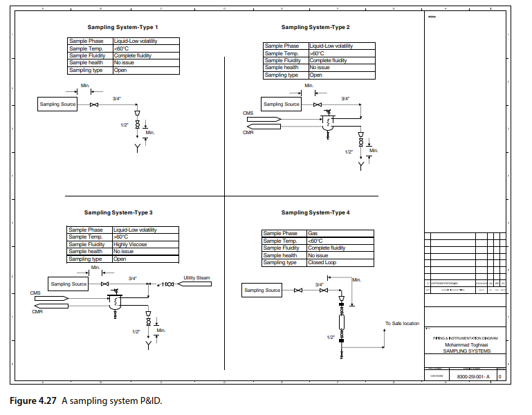
that do not appear on a PFD (e.g. sampling systems and HVAC systems). For these items, P&ID development basically means developing the BFD, the PFD, and then the P&ID. Although the BFD and the PFD of these items are not always drawn, designers should, at least, visualize
them in their mind before trying to develop the P&ID.
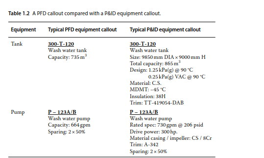
It is important to point out that the mechanical details of a plant are not shown on a PFD, only the process steps or process elements of the plant are shown. For example, even though we see a on a PFD, we do not introduce a tank as hardware here. What we are trying to say at the PFD level is, “we have something here that stores the liquid of interest.” It could be a fixed roof tank or floating roof tank, but in this stage of the project we do not know yet or we do not care to show it on the PFD. Because of this, the physical dimensions of the tank on a PFD are not mentioned; we only say that the normal storage liquid capacity of this tank is, for example, 500 cubic meters
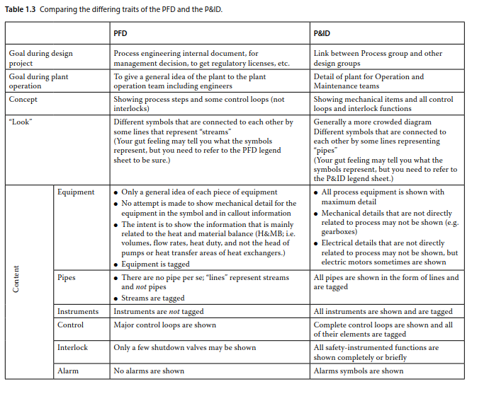
In a nutshell, the difference between equipment callouts on a PFD and on a P&ID is that on the PFD the data are operational information, while on the P&ID, the data are mechanical information. As a PFD is mainly a process engineering document, all its information are for normal operations of a plant. The P&ID is a document that illustrates the capability of the equipment. Table 1.2 shows the differences between one‐item callouts on a PFD and on a P&ID.
2.Management of P&ID Development:-
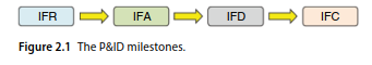
What is shown on the P&ID in the early stages of a project is a vague idea of a plant, whereas in the later stages of the project, the P&ID can finally be used for the construction of the plant. This last revision of a P&ID in a design project is Issued for Construction, or IFC. The P&ID goes through different milestones during a project: Issued for Review (IFR), Issued for Approval (IFA), Issued for Design (IFD), and IFC (Figure 2.1).
The first step is IFR. In this step, an engineering company has completed the primary P&IDs and lets the client review them. These P&IDs represent the first thoughts about a plant and will be used as a starting point.
Some engineering companies issue one other revision of P&IDs before this milestone, and it is known as Issued for Internal Review, or IFIR. The objective of this IFIR is to have a set of P&IDs for review by the engineering company without the participation of the client. Not all engineering companies issue IFIR P&IDs even though they do need to internally review the drawings before allowing the client to look them over. Companies do this without officially issuing a P&ID as IFIR; they simply perform the internal review based on the latest copy of the P&IDs.
2.1Required Man‐Hours for the Development of P&IDs:-
It is difficult to introduce a methodology for predicting the required man‐hours for P&ID development because each company may use its own methodologies for predicting the required man‐hours. The required manhours depends on the available tools in companies, the maturity and completeness of their P&ID development guidelines, and the skill of the designers.
he estimation of man‐hours is normally the responsibility of each group. Process, Instrumentation and Control, Drafting, Piping, Mechanical, Civil, and other groups estimate their own hours for P&ID development. However, in some engineering companies, only two groups (Process and I&C) consider and assign man‐hours under the category of P&ID development. The other groups generally do not assign specific separate manhours for their P&ID involvement; it could be because their involvement is not as large as that of the two main
contributors of P&ID development.
The Piping group has a specific role. On the one hand, they are mainly the “users” of P&IDs wherein one may
say they do not need any assigned man‐hours for P&ID development. They, however, may need to contribute to the P&ID development during detail stage of project. There are cases in which the Piping group design affects the P&ID. In such cases, the Piping group may need to
incorporate changes on the P&ID.
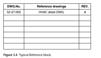
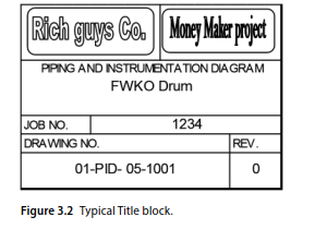
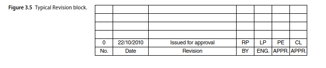
3.1P&ID Drawing layout:-
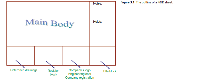
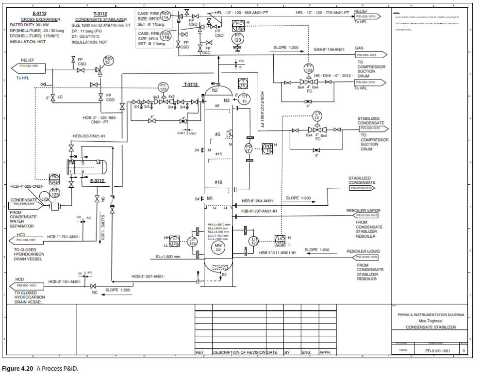
Figure 3.1 shows a typical P&ID sheet composed of different blocks. Companies may decide to have different blocks on their P&IDs, but their sheets should have at least a Title block and an Ownership block. The Title block tells the reader what something is, and the Ownership block
indicates who made the P&ID and for whom it was made.
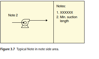
P&ID Design notes:-
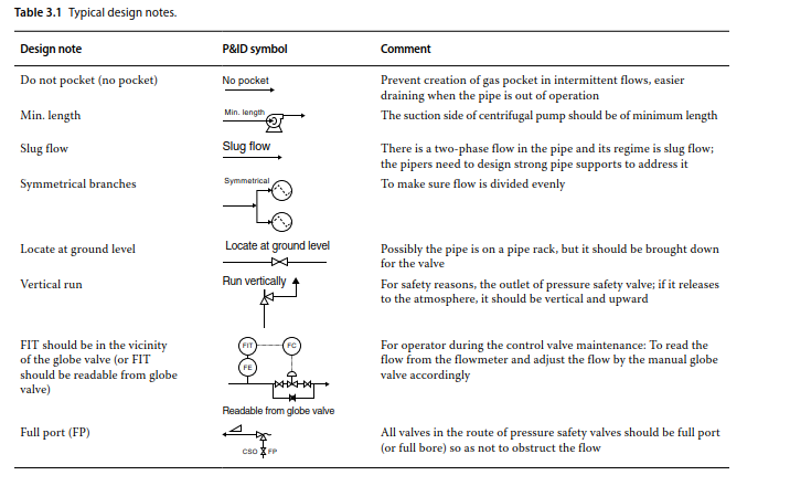
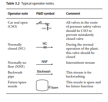
3.2P&ID operator notes:-
4.General Rules in Drawing of P&IDs:-
This Topic discusses what is shown in the main body of a P&ID sheet, which is followed by a discussion of the different types and names of P&IDs based on their content.
4.1 Items on P&IDs:-
Anything related to the process or anything needed to present the journey of raw materials into becoming final products should be shown on a P&ID.
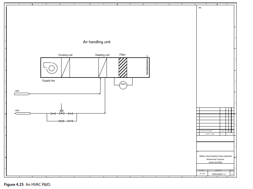
The above mentioned fact can answer many questions such as “Do we need to show the HVAC system of an indoor process plant?” In some cases, a portion or the whole plant could be indoors. In indoor plants, there can be an HVAC system in the building(s) to create a more suitable atmosphere for operators and equipment. As a general rule, very few details of an HVAC system are shown in such plants. However, in HVAC industries, the P&IDs can be drawn with their main purpose, that is, adjusting the air parameters.
There are basically four different items that can be shown on P&IDs:
1) Pipes and other flow conductors.
2) Equipment.
3) Instruments.
4) (Instrument and control) signals.
4.1.1 Pipes or Other Flow Conductors:-
Pipes and other flow conductors such as pipes, trenches, channels, and so on direct and transfer fluid from one equipment to another. The general rule is that the flow conductors of the main process fluids should be shown in the P&IDs along with the pipes. In a water treatment plant, the water flows in channels, so the channels are shown, too.
One important exception are tubes, which are not generally shown in P&IDs. However, there can be some.
The items for transferring bulk materials are generally categorized as “equipment” rather than “flow conductors.”
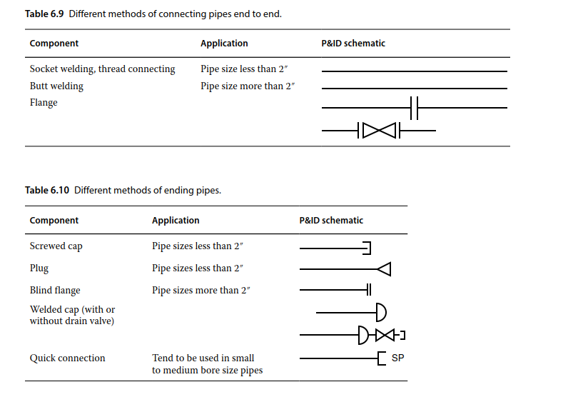
When it comes to showing pipe fittings, there is one rule: No pipe fittings are shown except tees, reducers, process flanges, and cap, plug, and blind flanges (Figure 4.1).
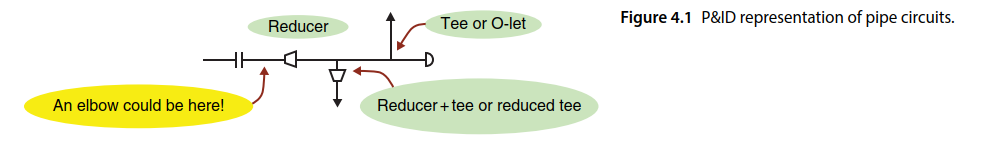
A straight piece of pipe on a P&ID could be a pipe circuit in‐field with a bunch of elbows. A straight piece of pipe in‐field can be represented as a line with several directional changes on a P&ID.
4.1.2 Equipment:-
The main players in processes are the equipment such as pumps, compressors, heat exchangers, and reactors. Containers can arguably be classified as equipment, too. Tanks and vessels are for process and/or storage purposes. All equipment should be shown on the P&IDs.
If the equipment, however, are purely associated with mechanical details that are not related to the process, they may not be shown on the P&IDs. Examples are a gear box associated with a mixer, small built‐in lubrication systems, and power hydraulic systems. In large compressors, the lubrication system can be large and a separate system. In such cases, the lubrication systems are shown, too. Equipment can be metallic, fiberglass, concrete, and so on, and in all cases, these should be presented.
4.1.3 Instruments:-
To implement every process, two requirements should be met: the process element (i.e. equipment) should be designed and tailored for a certain process and the control system should be formed to ensure implementation. If one of these is not followed, it is most likely that
the process goal will be only on paper.
instruments are the hardware that implement the control strategies in the plant.
4.1.4 Signals:-
Signals provide the means for instruments to communicate with each other. After deciding whether an instrument should be shown, the rule for showing signals would be easy: if there are two separate instruments and if there is a signal between then, this signal should be depicted.
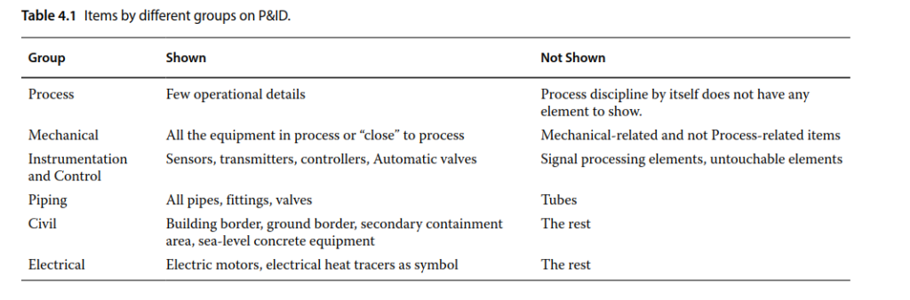
Table 4.1 outlines some guidelines on the items generally shown on the P&IDs for each group.
4.2 How to Show Them: Visual Rules:-
The first thing that should be answered in regard to the P&ID is what goes where and how it is displayed.
The first thing that a reader of a P&ID expects is legibility. A P&ID set is developed by the engineers during the design step of the project but will later be used in a process plant during operations. It is used by individuals with different levels of knowledge on and familiarity with a P&ID. A P&ID may need to be read by engineers, managers with management degrees, trade practitioners, and many others. It also should give enough information about the project that readers from different backgrounds will be able to understand it. A P&ID can be used during normal operations
or an emergency event. Therefore, a P&ID should be as legible as possible. Below are some rules of thumb regarding the visual aspects of P&IDs:
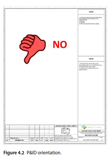
1) The P&ID sheet is almost always in landscape orientation (Figure 4.2).
2) Limit the number of main equipment shown on each sheet. A crowded P&ID should be avoided. Some companies try to limit the number of items on each P&ID to four or five, but other companies allow as many as 10.
3) A P&ID is a pictorial document, so minimize notes on the P&IDs (no “note‐stuffed” drawings).
4) Draw P&ID symbols as similar as possible to what an item looks like in reality and approximate to relative size, but remember, a P&ID is not drawn to scale (Figure 4.3).
5) Do not represent the real length of pipes on P&IDs. P&ID is a “Not To Scale” (NTS) drawing. Therefore, a short line on a P&ID could represent a few hundred meters of pipe.
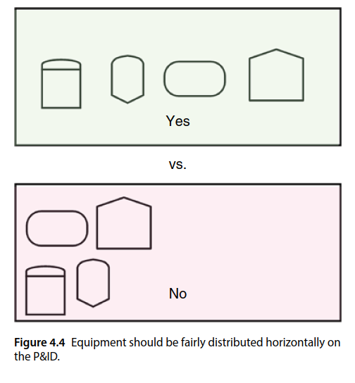
6) Do not “pack” symbols on one side of the P&ID sheet. The symbols should be fairly spread out.
7) Generally, an equipment is arranged horizontally on one level. On an ideal P&ID sheet, any imaginary vertical line should, at maximum, cross one equipment symbol. The P&ID will be too difficult to understand when equipment symbols are stacked on each other and the connection between the symbols and the equipment callouts are difficult to be identified. (Figure 4.4).
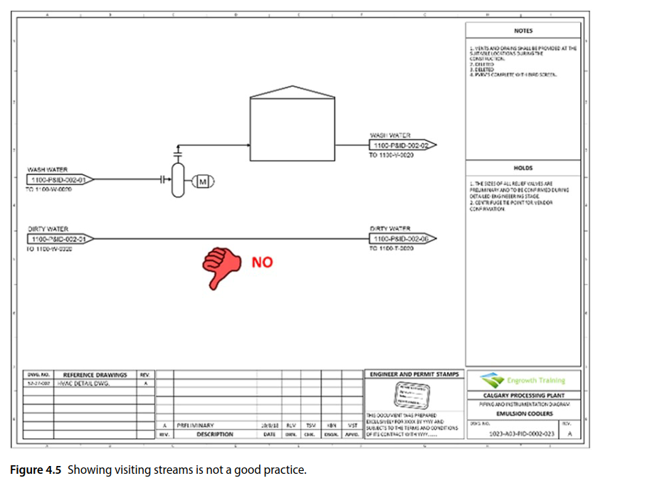
8) All the different elements on a P&ID sheet should be connected to each other. If a group of elements have no connection to the rest of elements, they can be drawn on another P&ID sheet.
9) No visiting stream is allowed. A visiting stream is a stream that has no connection with other items on
the P&ID. See Figure 4.5.
10) Do not try to present a P&ID in a way that follows geographical directions (e.g. north). P&IDs are drawings independent of these.
The rest of this section outlines the other visual issues
in drawing P&IDs and the general practices in dealing with these issues.


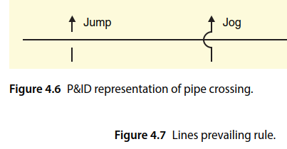
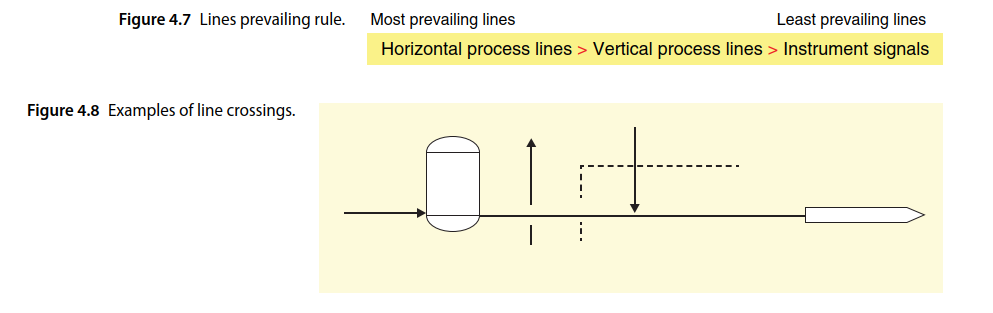
4.2.1 Line Crossing Over:-
Lines (in different forms) are symbols for pipes or signals. Crossing lines should be avoided or kept to a minimum, as well as changing the direction of lines. However, sometimes both are inevitable, and it is common to see lines crossing each other in P&IDs.
It is important to know that crossing lines in a P&ID does not reflect the reality of pipe routes in field. Crossing lines in the P&IDs is not acceptable aesthetically, but it is unavoidable in some cases. However, pipe crossing (or better, pipe clashing) in field shows a mistake in the design. A crossover could be shown in P&IDs in two forms, a “jump” or a “jog” (Figure 4.6).
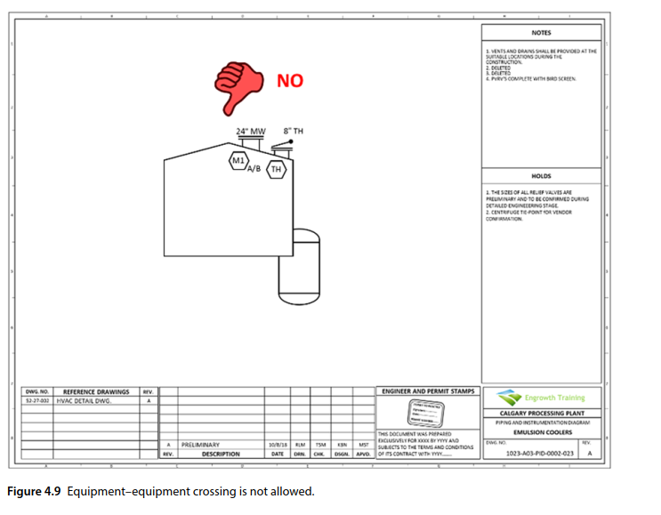
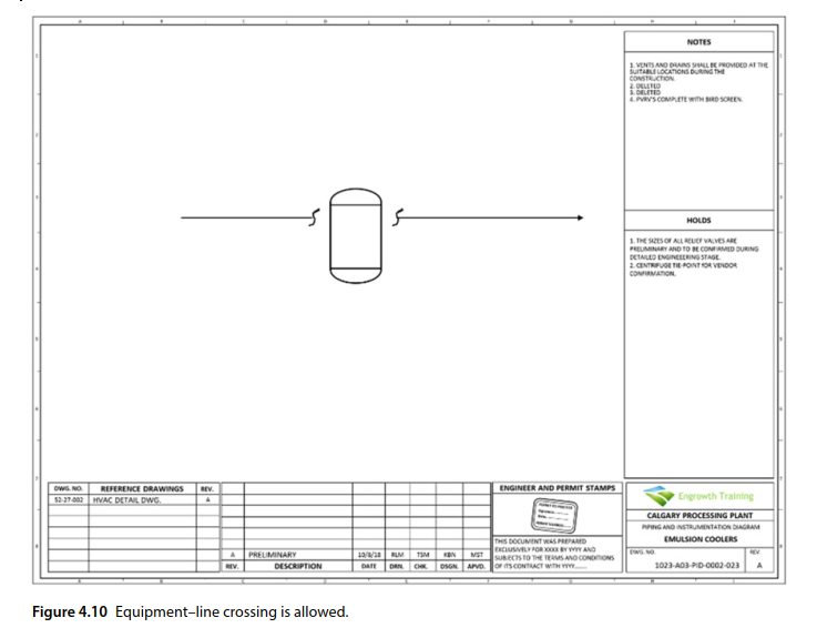
4.2.2 Equipment Crossing:-
Equipment–equipment crossing is not allowed on a P&ID (Figure 4.9).
Meanwhile, equipment–line crossing can be shown but it is not a good practice. This can be managed by using breaks on the line (Figure 4.10).
4.3 Item Identifiers in P&IDs:-
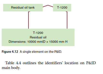
For each item to be shown on a P&ID, there can be a maximum of four different identifiers. This is like individuals in a society; each individual can be identified by different identifiers including name, ID number, picture or symbol, and brief information like eye color, hair color, height, and so on. Table 4.2 shows this analogy.
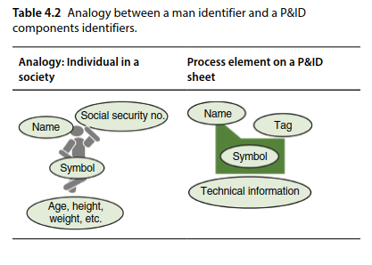
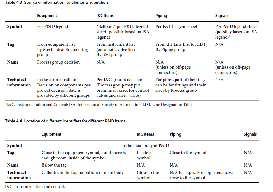
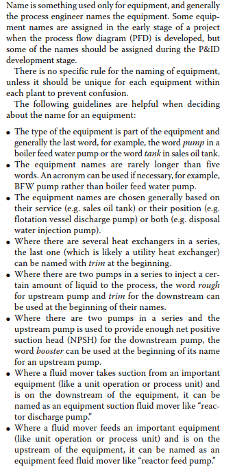
Figure 4.12 shows a tank with all four identifiers .However, neither all items on a P&ID have all identifiers nor their identifiers are separated from them. For example, a manual valve may only have symbol and no other identifier. In the pipe tag, some technical information can be seen, too. To be able to draw a P&ID, we need to know which identifiers are used for each item and where they can be found. Table 4.3 shows which identifiers are used by telling which identifier is provided by what group for the P&ID.
4.3.1 Symbols:-
Symbols are always based on the P&ID legend sheet but the legend sheet is not always the first P&ID sheet developed, so it may be difficult for designers to pick a symbol when there are no legends to refer to. This issue, however, is not always detrimental. Process engineers generally have some previous experience and also use symbols that can be understood using common sense. However, there can be an issue, especially if there are different groups working on different areas of a project. One group may choose different symbols for a single element. Therefore, communication plays vital role here.
Equipment symbols may have internals that may or may
not be shown. If shown, they should be a dashed line.
4.3.3 Name:-
4.3.4 Technical Information:-
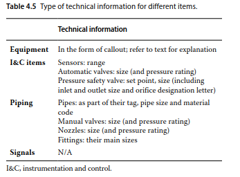
Technical information is information about an item on the P&ID. The number and nature of information required to be placed for each item can be decided by the client. However Table 4.5 can be used in lack of better information. It is important to consider that the amount of technical information should be kept at a minimum on the P&IDs. The P&ID is a pictorial document, and technical data should only be there to aid in the understanding of the symbols. If more numerical information about an item on a P&ID is needed, data sheets and other respective documents need to be consulted.
4.4 Different Types of P&IDs:-
There are primarily five different types of P&IDs: legend P&IDs, system P&IDs, network P&IDs, interarea P&IDs, and detail P&IDs. Although not all companies recognize the different types of P&IDs, the concept exists and needs to be understood.
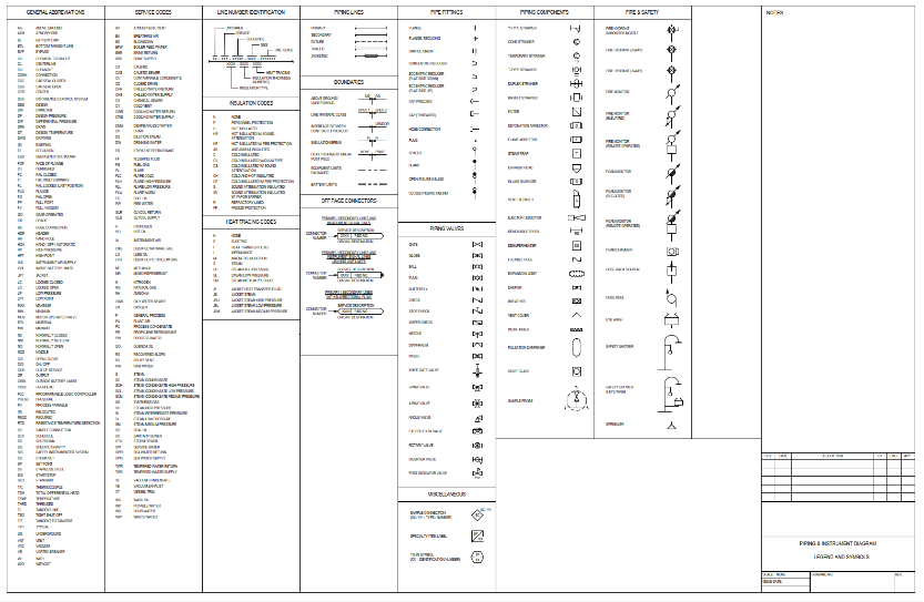
The legend P&IDs are a few P&ID sheets that introduce all the symbols and acronyms and their meaning. To be able to read and understand the P&IDs, there needs be one or more sheets showing the meaning of symbols and acronyms on the P&IDs.
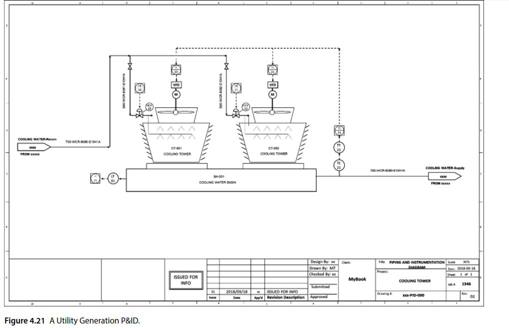
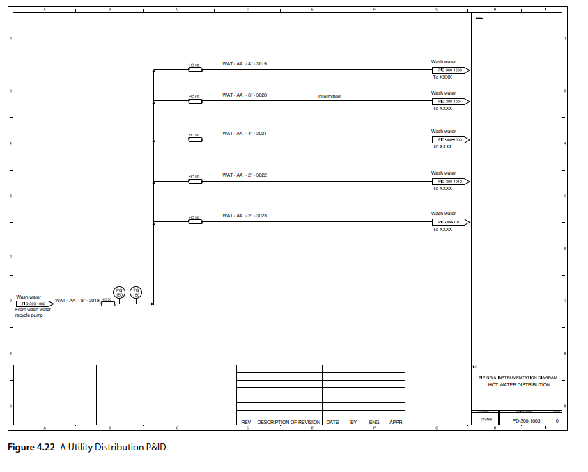
The network P&IDs are the P&IDs that show the distribution or collection of material within the plant units, for example, utility distribution (and collection) P&IDs, safety release gathering network P&IDs, fire water P&IDs, sewer collection system P&IDs, and blanket gas and vapor recovery unit (VRU) P&IDs. Some companies use other names for utility P&IDs such as utility distribution diagrams (UDD) or U&IDs. It is easy to
determine if a P&ID is a network P&IDs – these are mainly pipes and does not have equipment.
4.5 P&IDs Prepared in Engineering Companies Compared to Manufacturing or Fabricating Companies:-
The P&IDs prepared by manufacturing or fabricating companies can be different than the P&IDs prepared by engineering companies. P&IDs created by engineering companies are prepared for the purpose of erection, installation, and start‐up and should be kept in the plant for the life of the plant, whereas a P&ID made by manufacturing companies are prepared solely for construction.
The differences can be summarized as follows:
1) The P&ID set by manufacturing companies generally do not have auxiliary P&IDs. All the required details are shown on the main P&ID set. In many cases, vendors are not responsible for auxiliary systems.
2) The P&ID set by manufacturing companies tend to have more technical information. It is not strange to see the pressure range of a pressure gauge on a P&ID prepared by a manufacturing company. This is because manufacturing companies try to put as much as information on their P&IDs for other disciplines.
This helps keep all involved parties understand the P&IDs without looking elsewhere.
3) The P&ID set by manufacturing companies may have the brand name of items used on each P&ID sheet.
4) The P&ID set by manufacturing companies tends to have less design and operational notes. They may have less notes because of a closer relation with their design groups within their company. Also because the design groups work in one specific area, they are experts and
already consider the details of design requirements, which are in the Notes block of other P&IDs.
5) P&IDs created by manufacturing companies may have more detail regarding instrument air.
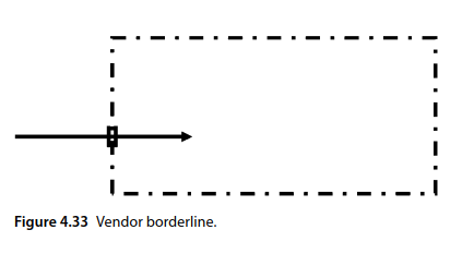
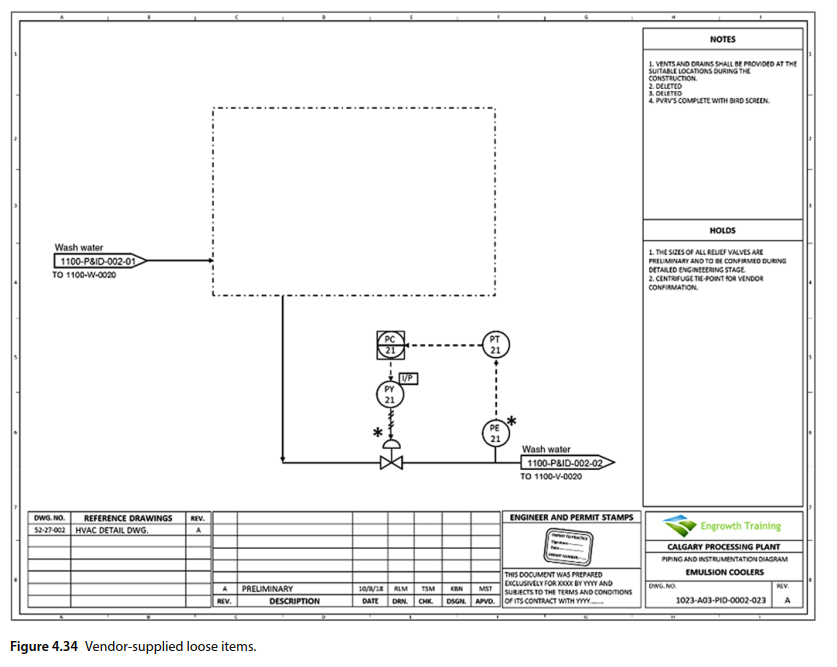
4.6 Dealing with Vendor or Licensor P&IDs:-
The engineering company responsible for designing a process plant and developing the P&ID most likely does not have any item it built. The engineering company buys pumps from one vendor, vessels from another vendor, and tanks from a third vendor. Therefore, all the
items on the P&IDs are supplied by the vendor. There is generally no “footprint” on P&IDs pinpointing the existence of vendors except in one important case. If there are several pieces of equipment by one vendor that are already assembled on skids or should be assembled in
the field by the vendor, it should be shown on the P&ID (Figure 4.33).
5.3 Plant Operations:-
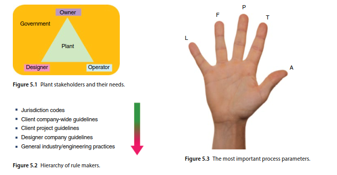
Operations are the fundamental reason for having a process plant. Therefore, operations should be clarified at the beginning. The concept of plant operations is a common topic in P&ID development and in plant design. A person involved in plant, equipment, or instrument design or in P&ID development should be familiar this topic.
Plant operation relies on all the parts of the process parameters to function according to design. So, what are the process parameters and what are their different levels?
5.3.1 Process Parameters:-
In any process, there are a number of different parameters to consider. The five most important process parameters are as follows (Figure 5.3):
● Level. Level is defined only for nonflooded liquid containers and flowable solid containers. It cannot usually be defined for other process equipment, like pipes. Level can also be defined for open channels.
● Flow rate. Flow rate is a parameter that is almost exclusively defined for pipes. However, when talking about “flow of a piece of equipment,” we refer to the flow in the inlet or outlet of the equipment.
● Pressure. Pressure can be defined for any piece of process equipment, including vessels and pipes.
● Temperature. Once again, temperature can be defined and specified for any part of the process.
● Analyte. Analyte is a parameter that shows the composition. Unlike other parameters, composition is not one definite parameter. It consists of a number of items that can be measured with process analyzers. This might be the pH of water, the octane number of gasoline, the amount of hydrogen sulfide in gas, the brix in
5.4 What Should a P&ID Address?
A P&ID should account for the full functionality of the plant in all stages of the plant life cycle, which can be outlined in four different phases: normal, nonroutine, inspection/maintenance, and the running without the item under maintenance.
For each process of the plant life phase, the three main elements of process plants – equipment, control system, and utility system – need to be designed properly.
1) Normal operation: In this phase all plant elements operate effectively and reliably. It means the functionality of equipment, containers, and piping are in their operating windows. In this step, the BPCS works to bring the item within normal conditions.
2) Nonroutine operation: In this phase, all plant elements operate but not “normally.” We can classify all these as nonroutine conditions. There may be low quantity of the product or a low‐quality product (off‐specifications product). In this stage, the SIS and safety relief valve may be triggered. This stage includes reduced capacity operation (system turned down), process upsets, start‐up, shutdown, and any other phase of operation, which is not considered normal operation.
3) Maintenance and inspection: In this phase, the plant or some of its items undergo inspections and maintenance. Enough provisions for ease of inspection, rejuvenation, and maintenance should be provided. These provisions can include a wide range of things (i.e. isolation, draining, purging, steaming‐out, or water flushing).
4) During maintenance on a piece of equipment, that piece of equipment is most likely nonoperational. The provisions should be provided to make sure the rest of plant is fully functional in the absence of that piece of equipment.
6.Pipes and Equipment:-
In general, all process industries have three main elements: equipment, utility generation and networks, and instrumentation/control systems.
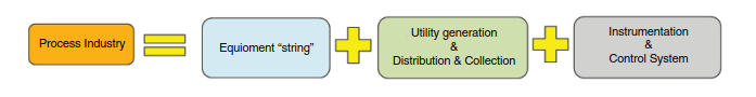
The first element is the string of equipment. In each plant, pieces of equipment are tied together to convert raw material(s) to product(s). In this context, the equipment could be pipes, vessels, tanks, pumps, heat exchangers, etc.
These pieces of equipment generally need external “help,” or utilities, to do their duty. For example, a pump needs electricity to operate, so in this case, electricity is considered as a utility. A heat exchanger may need a heat stream, like steam, to change the temperature of a process stream. In this example, “steam” is a utility.
All these utilities need to be generated in an auxiliary plant near the main process plant; this utility plant is called a utility generation plant. A utility generation plant is in nature the same as a process plant, but it only produces utilities.
There may be different types of utilities in each process plant, including electricity, steam, utility water, instrument air, utility air, cooling water, etc.
The generated utility in the utility generation plant should be distributed to different users or equipment In some cases, the “used utility” needs to be collected to save some money by recycling the utility by converting it to a “fresh utility” for other reasons. In such cases a collection network is also needed.
6.1Equipment:-
There are hundreds of different types of equipment in the different process industries. The types of equipment in an edible oil processing plant could be different from the equipment in an oil refinery; the equipment in a mineral processing plant could be different from the equipment in a waste water treatment plant. However, there are five main groups of equipment that are common in almost all process plants:
1) Fluid conductors: pipes, tubes, ducts
2) Valves
3) Fluid movers: pumps, compressors, etc.
4) Containers: tanks, vessels
5) Heat exchange equipment: heat exchangers, furnaces.
6.2Pipes:-
In process industries, to transfer fluid from point A to point B (e.g. equipment A to equipment B), a fluid conductor is needed. Pipe is the most common type of fluid conductor as it can transfer liquid, vapor, gas, or flowable solid. The fabrication process of pipes is different from tubes. For a small fluid flow, tubes are used, while for low‐pressure gases or air, ducts. The other fluid conductors are channels, chutes, and so on (Table 6.1).
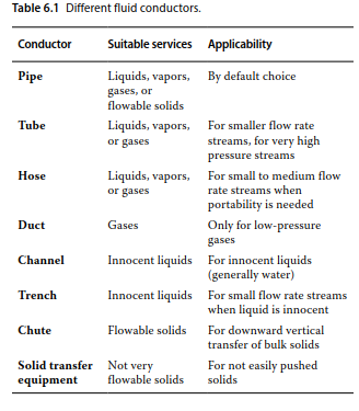
It is not difficult to transfer fluids, liquid, gases, and vapor, but flowable solids is. The word flowable is used for a non continuous version of solids. These solids could be in the form of granules, pellets, flake, powder, beads, chunk, and so on. They could be sugar or tomato in food industries or ore in mineral processing. Usually the smaller the solid particles, the easier they are to trans- port. To transfer a stream of iron ore in chunk form, we may need a bucket elevator rather than piping. Chutes are used for vertical or downward transfer of solids and semisolid materials. To summarize, transferring solids are generally done by equipment rather than by a simpleconductor.
In this topic, the main focus is on pipes.
6.3 Pipe Identifiers:-
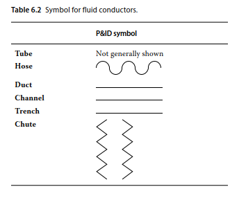
6.3.1 Pipe Symbol:-
The symbol for pipe is a line (Table 6.2). On P&IDs it is preferable to show pipes as vertical or horizontal lines rather than oblique. There are two features related to lines: their thickness and their arrowhead. On P&IDs, the thickness of lines gives more information about the pipe. A thick line represents a primary pipe, and a thin line means a nonprimary pipe. The decision whether a pipe is primary depends on the purpose of the plant.
Generally, primary pipes are used in the main feed and product of the plant, while nonprimary pipes are for other streams. It is important to know that the thickness of the line does not necessarily specify the diameter of the pipe. A thin line could be a 2‐inch pipe, a 6‐inch pipe, or even a 20‐inch pipe. However, primary pipes do generally tend to be large bore pipes.
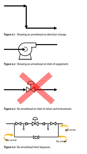
The other feature of line for pipe symbols is the arrowhead. The arrowhead shows the direction of flow in pipes during the routine operation. However, the question is, in which situations should the arrowhead be shown? The general rule is that the arrowhead should be shown in two cases:
1) Where there is a change in the direction of the line (Figure 6.1).
2) In the inlet of equipment (Figure 6.2).
It is important to consider we generally do not put an arrowhead on the inlet of valves or instruments (Figure 6.3). Some companies also do not put arrowheads on short loops around process or instrument items (Figure 6.4).
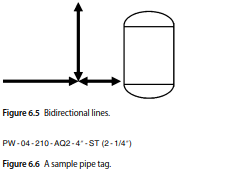
There are cases in which a pipe has different flow directions during different phases of routine operation. Because the arrowhead shows the direction of flow during routine operation, normal operation could be one stage of routine operation. For example, a sand filter that works in a semicontinuous mode may have different operation phases: filtration, backwashing, and retention. Then there are pipes that carry flows in a different direction in different phases of operation. Thus bidirectional lines may exist (Figure 6.5).
6.3.2 Pipe Tag:-
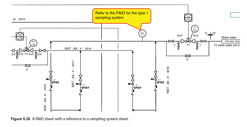
The second pipe identifier is a pipe tag. Pipe tags should be assigned to each piece of pipe and shown on P&IDs. The anatomy of pipe tag is specified by the project. Guidelines. Different information packs in the pipe tag will be discussed in Section 6.4. A sample pipe tag is shown in Figure 6.6. All the tagged pipes will be eventually listed in a document called a line list or line designation table (LDT).Three questions should be answered: Which flow,,conductors should be tagged? Which span of pipe route can be considered one piece of pipe? And, how is the pipe tag shown on a P&ID? These questions are answered here.
PW – 04 – 210 – AQ2 – 4″- ST (2 – 1/4″)
Figure 6.6 A sample pipe tag.
6.3.2.1 Do All Pipes Need to be Tagged?
Not all flow conductors on a P&ID set are tagged. Generally speaking, only pipes are tagged. The question to answer if a piece of flow conductor needs to be tagged is: Does it need to be hydrostatically (or pneumatically) tested before being put into service?
If the answer to this question is no, the flow conductor does not really need to be tagged unless it is long enough. One main use of pipe tags is for documentation of hydrotesting, which checks the integrity of a piping circuit. After the performing the hydrotest, all the tag names of the pipes in a piping circuit that pass the test should be recorded. If a pipe does not carry a tag, it may be missed for hydrotesting, which is a big mistake.
Table 6.3 outlines some example of pipes that are not generally tagged. Hydrotesting is performed on a larger integrated pipe, so these untagged pipes will be still tested. In another perspective, some stakeholders believe P&ID’s in an operating plant shouldn’t carry pipe tags at all! Plant operators claim that P&IDs are too crowded to be used during operation as some information should have been eliminated from the last revision of P&IDs before issuance for use, for example, the pipe tags because they are not useful during plant operation However, pipe tags are a very critical piece of information in critical plants like nuclear power plant.
6.3.2.3 How is the Pipe Tag Shown on a P&ID?
6.4 Pipe Tag Anatomy:-
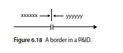
A tag number bears many information about a pipe. The anatomy of a pipe tag varies from company to company; however, the following information can usually be found in a pipe tag:
Area or Project Number-021,20
Commodity Acronym–Fire water -FW,
Pipe Material Specification Code-A1A,A2S
Pipe Size-400,200
Pipe Sequential Number-210,5010
Other Pipe Tag Information:-
The following can also be included in the pipe tags. Some are discussed in other topic of this book. Figures 6.16 and 6.17 show two examples of pipe tags.
● Insulation type and thickness (topic 17).
● Heat tracing type (topic 17).
● Whether the pipe is underground or aboveground
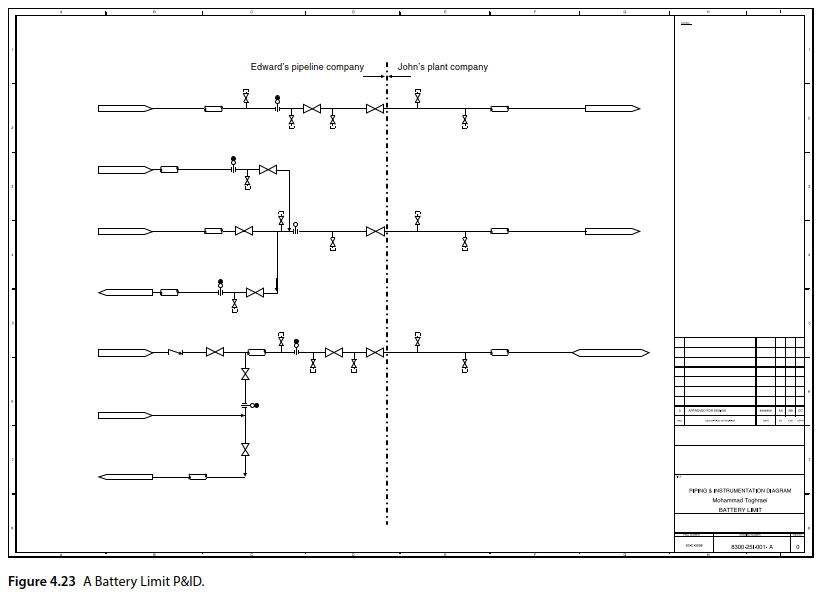
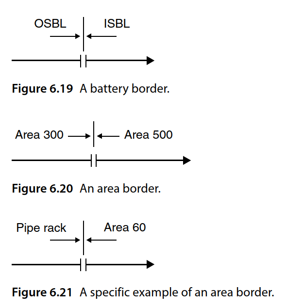
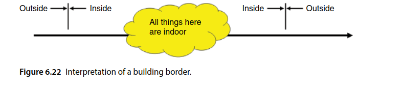
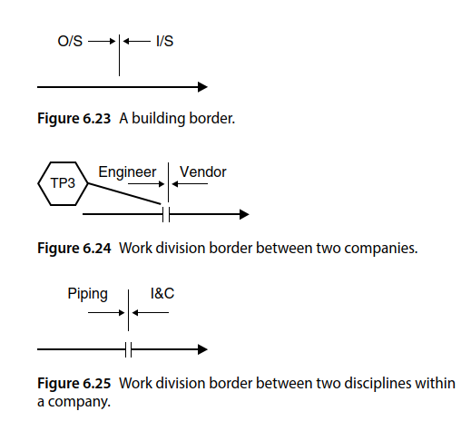
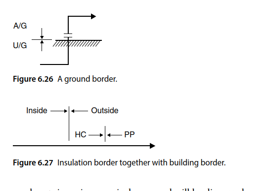
6.5 Pipes Crossing “Borders”:-
When or if a pipe crosses a border, this should be shown onthe P&IDs (Figure 6.18). There are six different borders that a pipe can cross, and these should be depicted on the P&IDs.
Battery limit border: See figure
Area border: See figure
Building border: See figure
Work division border:-See figure
Ground border: See figure
Spec break border: See figure
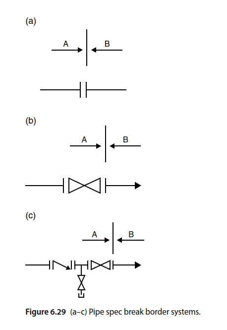
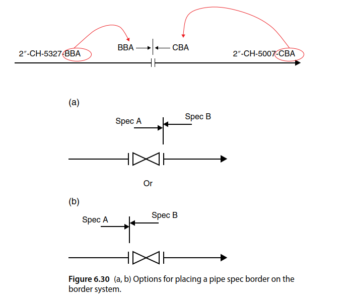
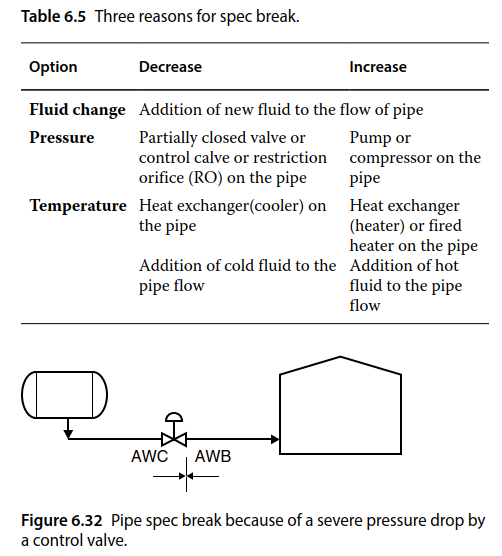
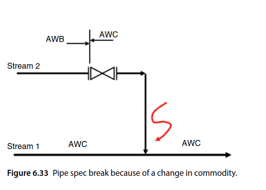
6.5.1 Reasons for a Spec Break:-
As it was mentioned, the pipe spec may need to be changed if the type of flowing fluid, the temperature, or the pressure of flowing fluid is changed. These changes together with other potential reasons for a change are listed in Table 6.5.
6.6 Pipe Route:-
Generally speaking, the real pipe route cannot be seen on the P&IDs. There are cases, however, that a special route should be considered for some routes based on engineering considerations. Such special pipe routes should be formally communicated with the Piping group (to develop proper
pipe models and isometric drawings) to make sure they will be implemented in the plant during construction.
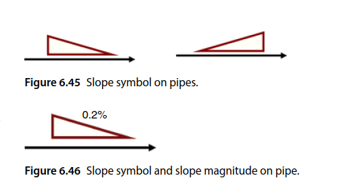
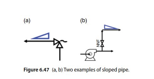
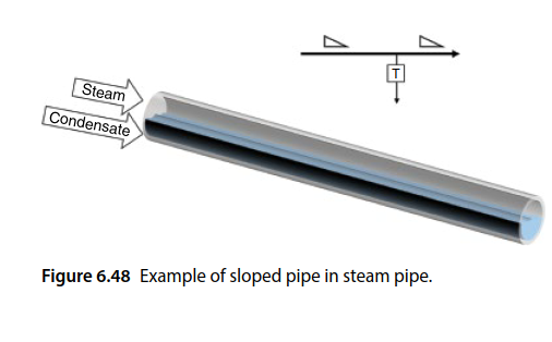
6.6.1 Slope
The slope on pipes can be important for horizontal pipes if a liquid or a two‐phase flows with a liquid component flowing inside of them. There is no slope for vertical pipes, and slopes on gas flows are not important. Generally speaking, horizontal pipes are used without a slope for different reasons, including the difficulty in handling the pipe elevation and pipe supports. Therefore, by default no horizontal pipe will ever have a slope.
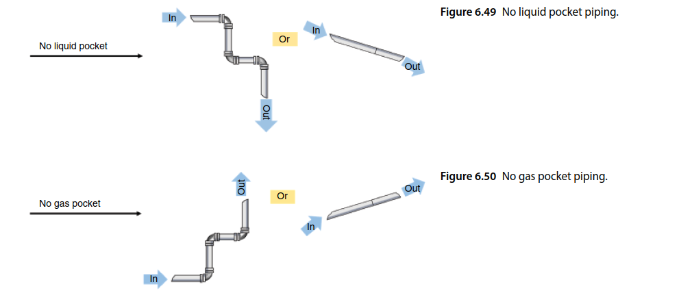
6.6.2 No Liquid Pocket:-
A pipe fully carrying a liquid flow with the chance of excursion of gas or vapor can be a candidate for no liquid pocket, means “design in a way that liquid pockets naturally flow and exit the pipe route during the routine operation of the system”. This phrase directs the pipe modeler to design a pipe route wherein the gas flow cannot trap a pocket of liquid anywhere in the pipe route (Figure 6.49). To respond to this requirement, a piping
modeler specifies a pipe route that is vertically downward or has a direct slope.
6.6.3 No Gas Pocket:-
A pipe fully carrying a gas or vapor flow with the chance of generation of liquid can be considered no gas/vapor pocket if the intention is to avoid a stagnant gas pocket in the pipe during the routine operation of the system. The term no gas/vapor pocket directs the pipe modeler to design a pipe route that the liquid flow cannot trap a pocket of gas anywhere in the pipe route (Figure 6.50). To respond to this requirement, a piping modeler specifies a pipe route that is vertically upward or has a reverse slope.
6.6.4 Free Draining (Self‐Draining):-
This note dictates the same requirements of no liquid pocket but during a system shutdown. This noteactually means to do the piping in a way that no liquid remains in the pipe after a system shutdown.
6.6.5 Free Venting:-
This note also dictates the same requirements of a no gas pocket but during a system shutdown. This note actually means design the piping in a way that no process gas remains in the pipe after a system shutdown. This note is less common than free draining note.
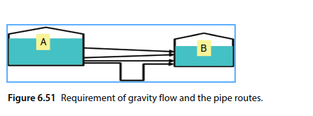
6.6.6 Gravity Flow:-
The note gravity flow is abused in many cases. Figure 6.51 shows a flow driven by gravity. In such an arrangement, the fluid flows from tank A to tank B as long as the energy in tank A is higher than in tank B, or the liquid elevation is higher in tank A than in tank B. So, the pipe route does
not change anything in this gravity flow. However if there is partial gravity flow, the pipe route should be a no liquid pocket.
6.6.7Straight Piping:-
This is a common note when dealing with flow meters. Flow meters generally have a required straight pipe in their upstream and downstream. Such a straight portion of pipe should be considered during the piping modeling. However, in the majority of cases, such note is not stated as the piping modelers are well aware of this requirement.
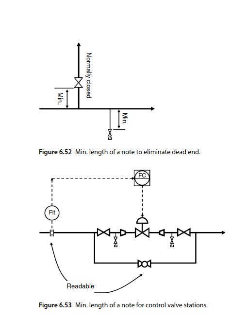
6.6.8 Minimum or Maximum Length or Distance:-
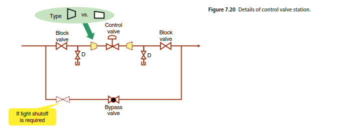
An example of this was discussed already in regard to the pipe spec border extension. The other example is minimizing the dead end portions on piping in a slurry or perishable fluid (mainly liquid) systems (Figure 6.52). The other example is the distance between the primary control element (sensor) and the manual throttling valve in the control valve stations. As will be discussed in next topic, during control valve off operation, an operator needs to watch the sensor and throttle the manual valve, hence bypassing the control valve. Then, the sensor and the manual throttling valve should be close to each other. Such a requirement could be detailed with a note about the minimum length for the pipe between
them or a “readable from valve” note near the sensor (Figure 6.53).
6.7 Dealing with Unwanted Two‐Phase Flow in Pipes:-
The design and implementation of systems in two‐phase flows are more difficult than single‐flow pipes. There are, however, cases in which a two‐phase flow is inevitable.
When the flow is intended to be a single flow, but then it turns out to be a two‐phase flow, the piping design is based on a single phase, and the two‐phase flow should be eliminated. There are three types of two‐phase flows liquid–gas, gas–liquid, and solid–liquid.
6.7.1 Liquid–Gas Two‐Phase Flow:-
In a liquid–gas two‐phase flow, there is a chance of liquid droplets in the main stream of gas or vapor. The problem arises when transferring a gas or vapor because a liquid can be generated and that is problematic.
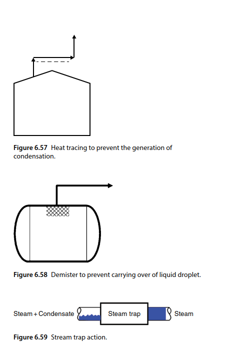
Such unwanted two‐phase flows may happen at different times. One is when gas comes off of a liquid surface, like in liquid–gas separators. The other case is when transferring hot vapors, like steam.
The first step in dealing with this problem is to prevent the creation of a two‐phase flow. For example, when transferring a wet gas, heat trace (dashed line beside the. main line) may be used. This solution can be seen in Figure 6.57.
The next method is to remove the generated liquid phase from the gas phase as soon as possible before the creation of a slug of liquids. One example is using a demister in a gas–liquid separator vessel as shown in Figure 6.58. For gas streams that come off of a liquid sur- face, there is always the chance of carrying liquid droplets over into the gas stream.
The other example is using steam trap in steam distribution piping networks. Steam traps remove water con-
densation from the steam (Figure 6.59.
6.7.2 Reducers (Enlargers):-
The goal in using reducers or enlargers is to increase or decrease the pipe size (pipe diameter). There are at least four situations that reducers or enlargers are used.
The first situation is in the case of tying‐in one or more pipes to another pipe and branching a pipe to more pipes. In these situations, a reducer or enlarger needs to be used (depends on the case) to keep the same velocity in the pipe after adding or deducting fluid flow from the pipe.
If a pipe needs to be branched off to other pipes, it means that a portion of the flow will be directed from the main pipe (header) to other pipes, leading to the decrease in the flow in the main pipe. If the diameter of the pipe is not decreased, the velocity of fluid in the pipe will be
decreased, which is not a good idea. Therefore, the reducer is used to adjust the pipe size with the new reduced flow rate in the main pipe or header. The reducer should always be placed after pipe branches and not before them. This can be seen in Figure 6.76a.
In a tying‐in situation, there are one or more pipes that merge in the main pipe or header. In this situation, the flow rate of the main header is increased after the addition of flow through the tying‐in pipes. Again in this case, an enlarger is used. The important point here is
that the enlarger should be placed before the tying‐in pipes not after them, as in Figure 6.76b.
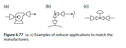
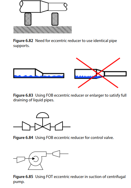
The second situation that a reducer or enlarger is used is when a pipe is connected to a piece of equipment or instrument. There are some cases that the equipment flanges do not match the pipe flanges; therefore, a reducer or enlarger needs to be able to connect pipe to a piece of equipment, such as connecting suction piping to a centrifugal pump or connecting discharge piping to the centrifugal pump. Other examples are piping connections to inlets or outlet of pressure safety valves and the pipes upstream or downstream of some control valves. These examples are shown in Figure 6.77.
6.7.3 Three‐Way Connections:-
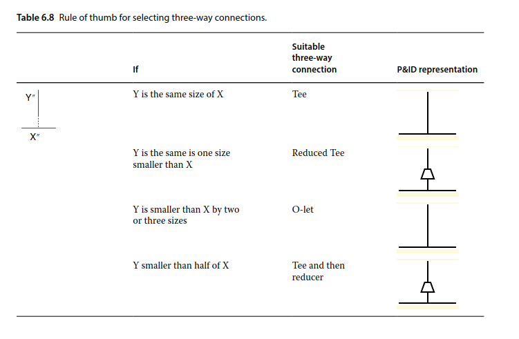
When there is a pipe arrangement with multiple sources or multiple destinations, the concept of tying‐in and branching off comes to the picture. Both of these concepts boil down to the question: How is a pipe connected to the middle of another pipe? Generally the response would be a requirement for a three‐way connection. But there are several types of three‐way connections. To know which type of three‐way connection should be used, a P&ID developer needs to consult the branch table available in the piping material spec table of the project. There are different fittings available to do that including tee’s, reduced‐tee’s and different types of O‐lets (e.g. Weldolets, Threadolet).
However, Table 6.8 can be used in deciding on the type of three‐way connection to be used, and it also shows the representation of different three‐way connections on P&IDs.
7.Manual Valves and Automatic Valves:-
7.1 Valve Naming:-
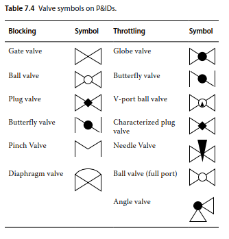
Valves are named based on their action on the service fluid (e.g. throttling valve, stopping (blocking) valve, or diverting valve) or based on their operating mechanism (e.g. motor‐operated, solenoid, or manual valve).
Valves can also be named based on their plug type; they can be a gate, globe, or butterfly valve. Valves can also be named based on the valve’s location in the piping (e.g. foot or root valve) or on its duty in the process (e.g. shutdown, blowdown, or flow control valve).
7.2 Valve Functions:-
Valves are piping appurtenances that actively affect flows. Active means the valve has a movable part. For example, a gate valve has a moving stem, and a check valve has a moving flap.
Any valve with moving mechanism that does not take order from the outside of the valve can be categorized as special valve. Check valves, air release valves, and excess flow valves are examples of special valves. Special valves are a large group of valves that have specific function. A
few subgroups of special valves will be discussed at the end of this topic. Special valves are diverse, which makes it difficult to classify them, but other valves can be
easily categorized.
7.3valve Symbol:-
7.4. Valve Selection:-
There are plenty of resources to help designers find the appropriate type of valve. A quick‐and‐dirty outline to find the most suitable type of valve for a specific application follows.
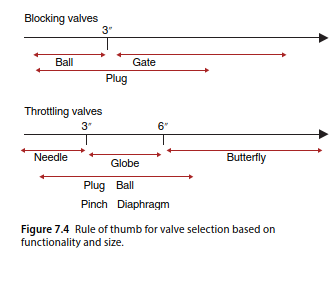
The first step is deciding if the valve should be blocking or throttling. The process designer decides the type of valve (blocking or throttling) based on the expected functionality of the valve. Generally speaking, the majority of manual valves in process plants are blocking types.
If there are manual throttling valves, they are mainly on non‐primary pipes. The automatic valves (or remotely operated valves) could be either blocking or throttling depending on the expected function of the valve.
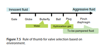
Figures 7.4 and 7.5 show the rules of thumb for deciding on the plug type of valves based on required size and the environment.
Generally speaking, a gate valve is used as default choice for a blocking valve, unless it is for very small sizes (e.g. 3″) that a ball valve is used because miniature gate valves are expensive. Plug valves could be used in all the ranges, but they are not as common as gate or ball
valves.

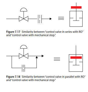
7.5 Control Valves and RO Combinations:-
A control valve can be combined with RO in two basic forms: in series and parallel. When an RO is placed in series with a control valve, it limits the maximum flow through the control valve when it is wide open. The same goal can be achieved by buying and placing a control valve with mechanical stop (Figure 7.17).
A control valve can also be limited in the wide open situation by implementing electrical or software stops through the control system. An RO in parallel to a control valve warrants a specific flow going downstream irrelevant of the control valve stem position, even when it is
fully closed. The same goal can be achieved by placing a control valve with mechanical stop (Figure 7.18). A control valve can also be limited in the fully closed situation by implementing electrical or software stops through the control system.
7.6 Control Valve assembly:-
8. Provisions for Ease of Maintenance:-
P&ID development for the purpose of inspection and maintenance was briefly discussed in topic 5. This
concept, however, is so important it needs a topic devoted to it.
This topic is about the required provisions that should be considered in P&IDs to facilitate an inspection and/or maintenance operation.
These provisions are used for the purpose of facilitating inspection and maintenance, and also sometimes as part of a shutdown system. The instrumentation requirements of safe shutdown are mentioned in another topic but here the process requirements are mentioned.
In this topic we discuss the requirements of three elements of each process plant: equipment, utilities and instruments regarding ease of maintenance and inspection.
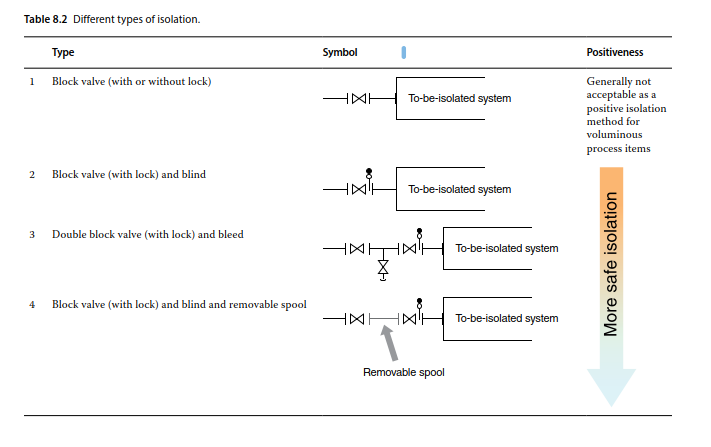
8.1 Isolation:-
When deciding on isolation systems, three questions need to be answered:
1) For what equipment should it be added?
2) Which type of isolation system should be used?
3) Where does it need to be placed “around” the equipment?
8.1.1 Requirement of an Isolation System:-
The first question that needs to be answered regarding the need for an “isolation system,” for a piece of equipment or a portion of a plant, is whether it is necessary to do something on that piece while the rest of the plant (or unit) is operating or not.
To answer this question, two parameters must be compared with each other: MTBF (mean time between failures), and “time interval between turn‐arounds.”
For example, a company may state that the MTBF for control valves in their refineries in the Middle East is six months. This means that, based on their experience, a typical control valve will break down every six months and will need to be repaired.
Turn‐around is the practice of shutting down the whole plant for a few months to do complete servicing and maintenance on all of its equipment
The time interval between turn‐arounds used to be one or two years, but now companies try to push it to four to six years.
Now the answer to the question is: if the MTBF of a piece of equipment is shorter than the time interval between turn‐arounds, then there is a need for placing an isolation system around the equipment.
It is obvious that if a piece of equipment will break down every three years, but the whole plant is planned to be shut down for turn‐around every two years, there is no need for an isolation system. As was mentioned, isolation is needed “if a piece of equipment needs repair while the rest of plant is operating.”
Therefore providing isolation valves is not necessary for all the equipment in a plant. Isolation valves are required to isolate the equipment from the rest of plant if we know this equipment needs “off‐line care” in a period shorter than the plant turn‐around period.
8.1.2 Type of Isolation System:-