Table of Contents
What Is Simply Supported Beam?
A beam supported on the ends which are free to rotate and have no moment resistance is known as a simply supported beam.
The simply supported beam is quite possibly the most simple construction. It includes just two supports, one at each end. One is a pinned support and the other is roller support. With this setup, the beam is hindered from any upward development at the two closures though it is permitted to pivot unreservedly. Because of the roller support, it is additionally permitted to grow or contract pivotally, however, the free even development is forestalled by the other support.
Simply Supported Beam can not move horizontally or vertically.
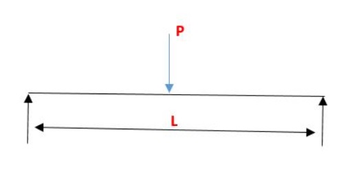
A Typical simply supported beam has two supports, one at each end. In the below-given figure, one end is pinned supported and the other is roller support.

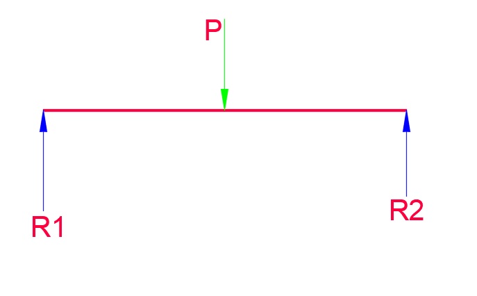
In the below figure you can see a simply supported beam with a point load.


As we know, point load acts on the center of the beam.
Hence, R1=R2=P/2
Simply Supported Beam Deflection
Deflection of a simply supported beam indicates how much it bends or sags when a load is applied to it. The deflection depends on factors like the load, the material of the beam, and its shape.
To calculate the deflection of a simply supported beam, we can use a numerical formula called the formula for a uniformly distributed load:
δ = (5 * w * L^4) / (384 * E * I)
Where: δ is the deflection (how much the beam bends) w is the load per unit length (e.g., pounds per foot) L is the length of the beam (e.g., feet) E is the modulus of elasticity of the beam material (a measure of its stiffness) I is the moment of inertia of the beam’s cross-section (a measure of its resistance to bending)
By plugging in the values for the load, length, material properties, and cross-sectional properties of the beam into this formula, we can calculate the deflection. It’s important to note that this formula assumes a uniformly distributed load along the beam and certain simplifying assumptions about the beam’s shape.
Calculating beam deflection using this formula provides an estimate of how much the beam will bend under the given load. Structural Engineers use this information to ensure that the deflection remains within acceptable limits to ensure the structural integrity and performance of the beam.
Read More:
