The Atkinson cycle engine is a kind of internal combustion engine. The Atkinson cycle is primarily designed to improve the efficiency of four-stroke gasoline engines with one specific improvement. This cycle is designed to utilize the power generation portion of the cycle while minimizing fuel consumption during the intake stroke.
Although the four main stages of the Otto cycle still exist, Atkinson has introduced a new sequence of closing the intake valves during the compression stroke. Leaving the intake valves open a little longer effectively reduces the displacement of the engine during the intake process, but maintains the maximum expansion ratio during the combustion or expansion stroke. This allows the engine to extract maximum energy from the ignited air/fuel mixture before the mixture remains in the chamber.
Table of Contents
Work Concept of Atkinson Cycle:
The Atkinson cycle works in the same way as the Otto cycle. However, this is a modified version of the Otto cycle. The Atkinson cycle works as follows.
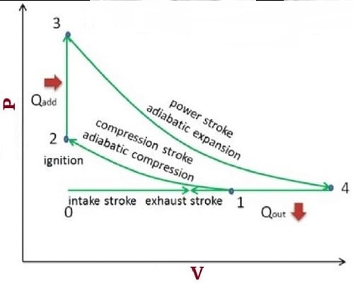
- Adiabatic compression (compression stroke): First of all, the piston helps the engine suck the fuel-air mixture into the cylinder from the outside. The piston then moves upward (from BDC to TDC), compressing the air-fuel mixture. While the piston moves upward (from 1 to 2), it compresses the mixture by increasing its temperature and pressure. However, during this process, the enthalpy of the air-fuel mixture remains constant and the volume decreases (see figure below).
- Isochoric compression (ignition phase): When the piston and the compressed air/fuel mixture reach point 2, an external heat source heats the compressed mixture. This ignition increases the enthalpy and pressure of the air-fuel mixture. However, no change in volume occurs at this stage. This phase is similar to the isochoric contraction phase of the Otto cycle. In this case, the piston moves more and compresses the mixture without changing its volume.
- Adiabatic expansion (power stroke): After the ignition process, the working stroke begins. At this stage, a gas (combusted air-fuel mixture) acts on the piston, moving the piston from TDC to BDC. The downward movement of the piston causes the gas to expand, and the downward movement of the piston rotates the crankshaft, which further rotates the flywheel. In this process, the volume of the gas increases and the pressure decreases. This process is known as entropy because the enthalpy does not change.
- Isobaric exhaust (exhaust stroke): The goal of the final Atkinson cycle is to keep the pressure inside the cylinder equal to atmospheric pressure at the end of the expansion stroke. In this cycle, there is no decompression in the cylinder as in the Otto cycle. After this exhaust stroke, the piston moves from BDC to TDC, and the entire cycle repeats.
Different Types of Atkinson Cycle Engine
- Atkinson Differential Engine
- Atkinson Cycle Engine
- Atkinson Utility Engine
1. Atkinson Differential Engine
Unlike the improved version, this cycle was implemented with an opposed-piston engine (Atkinson differential engine). In this case, one crankshaft was connected to two opposite pistons via a non-linear connecting rod.
During a half revolution, one piston remains stationary, and the other piston approaches and returns. At the same time, in the next half revolution, the second piston goes to a uniform state, and the first one approaches and returns.
So, at each revolution, one piston of the Atkinson differential engine performs the compression and power strokes and the other piston performs the exhaust and intake strokes.
2. Atkinson Cycle Engine
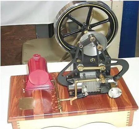
In 1887 Atkinson invented another engine he called the “cycle engine”. It had cams, poppet valves, and an eccentric lever that produced four piston strokes for every turn of the crankshaft. This engine’s Atkinson cycle had shorter intake and compression strokes than power and exhaust strokes.

Circulation motors have been manufactured and sold by British motor manufacturers for many years. Atkinson also has production permits for other companies.
3. Atkinson Utility Engine
Atkinson developed a third engine known as the “Utility Engine”. Atkinson’s second engine (circular) was efficient but had a leverage system that was very difficult to balance for quick operation. So Atkinson felt the cycle should be changed to better suit the higher-speed engines.
After improving on the previous model, Atkinson developed a new model called “Utility Engine”. With this new design, he eliminated the connecting rod and created a more balanced, more traditional engine that could run at around 600 rpm and generate power with every revolution. His “circulation engine” had a proportionally longer expansion stroke and shorter compression stroke.
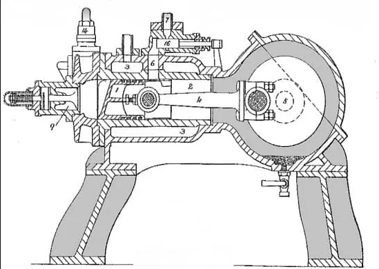
The operation of a general-purpose engine is very similar to that of a standard two-stroke engine, except that the exhaust port is centered on the stroke.
In this design, the cam valve on the power stroke (which does not open until the piston is close to the end of the stroke) stops the backflow of pressure as the piston passes through the transfer valve. This exhaust valve opens when the piston reaches the bottom of its stroke.
When the piston returns to its compression stroke, the exhaust valve opens and fresh air fills the combustion chamber, displacing the exhaust gas until the exhaust port is closed by the piston.
When the outlet or exhaust port is closed, the piston begins to compress the air remaining in the combustion chamber.
A small fuel pump injects fuel during compression. The ignition source, like other Atkinson engines, was a hot pipe. This design provides a two-stroke engine with high power and short compression stroke.
The efficiency of the Atkinson Cycle
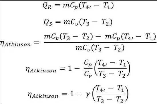
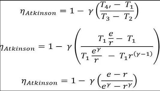
The performance of the Atkinson cycle may be calculated with the aid of using the below-given formula:

Where,
W = Work done by the system = QS – QR
In the above equation:
QR = Heat rejected by the system
QS = Heat added to the system
Expansion Ratio (e) = V4’/V3
And
Compression Ratio (r) = V1/V2
For the isotropic compression processes (1 to 2):
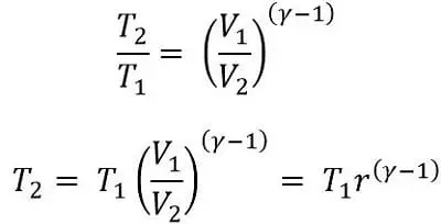
For the Isochoric compression process (2 to 3):
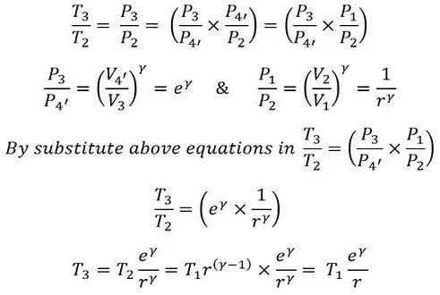
Adiabatic expansion (3 to 4):
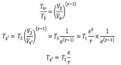
Substitute the values of T4, T2, and T3 into the efficiency formula. Substituting these values, the final efficiency formula is:
Advantages of Atkinson Cycle
- Conventional automobile engines operate in the partial load range. The use of the throttle valve is particularly convenient and flexible for controlling the flow of fresh air into the cylinder. However, the throttle valve creates a large vacuum in the intake manifold, resulting in significant air loss in the intake valve. If you can control the damage caused by throttling, you can save 15%-20% on fuel consumption.
- The Atkinson cycle effect has been shown to be an important way to improve part-load fuel economy by controlling engine load and reducing pumping losses.
- It is suitable for hybrid vehicles because the electric motor compensates for power loss at low speeds.
- The Otto cycle has a lower compression ratio than the Atkinson cycle expansion ratio. Therefore, the Atkinson engine is more efficient.
Disadvantages of Atkinson Cycle
- Atkinson cycle engines consume less fuel but produce less power.
- This cycle has a low compression ratio.
Difference between the Atkinson cycle and Otto cycle
| Atkinson Cycle | Otto Cycle |
|---|---|
| An Atkinson cycle has better performance than the Otto cycle. | An Otto cycle is much less efficient. |
| It consumes much less fuel; therefore, it generates low power. | This engine has excessive strength as it has an excessive compression ratio. |
| This engine consumes very little fuel. | It consumes a lot of fuel. |
| It has a better growth ratio than the compression ratio of the Otto cycle. | The Otto cycle has a better compression ratio than the compression ratio of the Atkinson cycle. |
