A heat engine operating in a Carnot cycle is called a Carnot engine. The Carnot cycle provides an estimate of the maximum possible efficiency of a heat engine operating between two reservoirs (hot and cold), while converting heat into output work.
In 1824 Nicolas Leonard Sadi Carnot invented the Carnot engine. This engine is known as the Carnot engine after its inventor Sadi Carnot.

Carnot engines are ideal engines that use reversible mechanical and heat exchange processes. This statement means that the engine can complete its motion and return to its original state without an increase in entropy (without loss of energy). For the engine to return to its original state without losing energy, it must be in thermal equilibrium for the entire cycle.
Following are a few phrases for the lifestyles of the Carnot engine:
- Mechanical interactions: In the process of mechanical interaction (Q=0), there is no heat transfer because the energy is not dissipated by friction. This process is called adiabatic process.
- Thermal interaction: In the process of thermal interaction, heat transfer occurs very slowly (called quasi-static). This means that the temperature difference between the inlet/outlet and the heat in the system is approximately equal, which means that the heat transfer takes place over an infinitely long time. In thermal interaction, the internal temperature of the system must be constant. Therefore, this process is called isothermal.
Engines that use the above interactions are called Carnot engines. This motor is a “fully reversible motor” with the highest thermal efficiency (ηmax).
Table of Contents
How It Works?
The Carnot engine operates based on the following Carnot cycle:
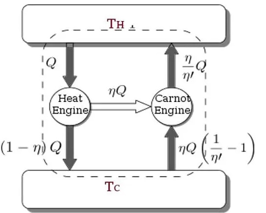
- The efficiency of an irreversible heat engine operating between two reservoirs is always lower than a reversible Carnot heat engine operating between two similar reservoirs.
- Any reversible heat engine operating between two identical reservoirs will have the same efficiency.
To increase the thermal efficiency of a gas power plant, the temperature of the combustion chamber must be high. For example, turbine blades cannot withstand hot gases, leading to premature fatigue.
Carnot Cycle Description:
A Carnot cycle works withinside the following 4 stages:
Now lets take a look about these 4 stages of carnot cycle.
1. Isothermal Expansion:
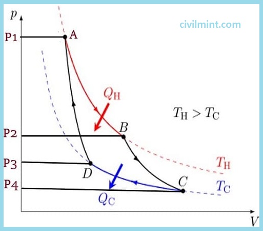
The line from A to B in the diagram above represents the isothermal expansion process. The word “isothermal” is a combination of “isothermal” and “thermal”. The term “isothermal” means the same thing, “temperature” means heat, and the term “isothermal” means no change in temperature.
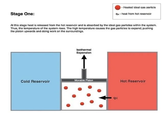
During this isothermal expansion, the gas expands and this expansion acts on the environment, moving the piston upward. During this process, the gas pressure decreases from P1 to P2 (see figure above). However, the temperature of the gas does not change during this whole process. Therefore, it is called isothermal expansion (expansion at constant temperature).
During this isothermal expansion, the gas absorbs thermal energy QH from the hot reservoir, increasing the entropy (energy) of the gas.
2. Adiabatic Expansion:
When the isothermal process is complete, the isentropic process begins (from B to C). For the isentropic step, it is assumed that the cylinder and piston are thermally isolated. This step is known as an “adiabatic” process because heat cannot enter or exit the cylinder and piston. Simply put, there is no heat transfer in this process.
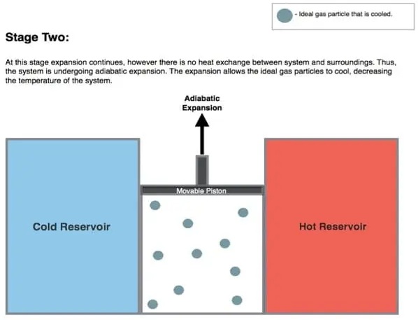
During adiabatic expansion, the gas expands continuously. The pressure drops further from P2 to P4 (shown in the diagram above), increasing in volume and decreasing in temperature. This is because some of the internal energy is lost in a similar way to the work done.
This gas expansion process further pushes the piston upwards, affecting the environment. In the absence of heat input, gas expansion cools the gas and converts its temperature to a “cold” temperature (Tc).
3. Isothermal Compression:
In this process, the environment acts on the gas that transfers heat from the system to the cooling reservoir. During isothermal compression, the temperature of the gas does not change. However, the pressure increases from P4 to P3 (see diagram above) and the gas volume decreases. This process causes thermal energy (Q2) to move from the system to the cooling reservoir and the entropy of the system drops.
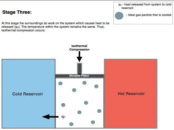
The work during isothermal compression is less than the work done to the medium in step 1. This is because this compression process starts at a low pressure so that heat is easily transferred from the system to the cooling reservoir and some energy is used in this process.
4. Adiabatic Compression (D to A):
In the diagram above, the line from D to A represents the adiabatic reversible compression process. This process assumes that the piston and cylinder are insulated again and the hot reservoir is removed.
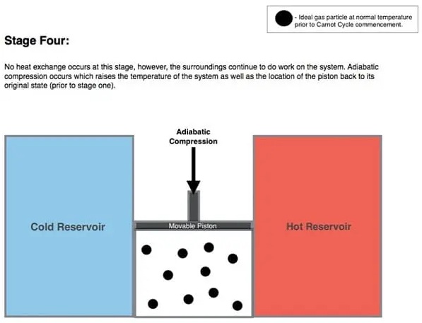
During this stage, the medium continuously works on the gas, moving the piston down. As the piston moves further downward, it continues to compress the gas and increases the temperature and pressure from P3 to P1 (see figure above). This process increases the internal energy of the gas, compresses the gas, and raises the temperature from Tc to Th. Entropy does not change in an adiabatic process. At the end of this process, the entire cycle is repeated.
Carnot Theorem
As per carnot theorm:
- Any reversible heat engine operating between two identical reservoirs will have the same performance.
- A reversible Carnot heat engine operating between two reservoirs outperforms a non-reversible heat engine operating on the same reservoir.
- Here is the maximum efficiency of the Carnot engine.
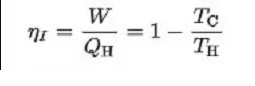
Where,
TH = Hot reservoir temperature
TC = Cold reservoir temperature
QH = Heat supplied to the system
W = Work done by the system
The performance of a Carnot engine varies in step with the temperature of the bloodless and warm reservoirs. It doesn`t depend upon the running fluid nature.
Efficiency of the Carnot Engine
Carnot efficiency refers to the most thermal efficiency that a Carnot warmth engine can gain in step with the second rule of thermodynamics. In 1824, Sadi Carnot added this regulation. He got here up with the concept of maximizing the performance of a warmth engine.
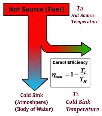
Sadi Carnot developed the Carnot engine, the so-called Carnot engine, that could theoretically provide this performance. The efficiency of the Carnot engine depends on the temperature in the low temperature (TL) and high temperature (Tc) reservoirs (see diagram below).
The following formulation can calculate the most performance of the Carnot cycle:
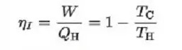
TC = Temperature of the cold reservoir
TH = Temperature of the hot reservoir
As can be seen from the above equation, the efficiency of the Carnot cycle can be increased by decreasing the value of TH or increasing the value of TL.
The Carnot cycle shows that the heat engine can achieve 100% efficiency when Tc = 0K. This 100% is only possible when the coolant temperature is absolutely zero, but theoretically and practically impossible.
Real heat engines cannot achieve as high efficiencies as Carnot engines. Carnot engines can reach practical efficiencies of up to 0.7. This is the best performance.
Modern diagram of Carnot Engine
The diagram below shows a block diagram of the Carnot engine. In 1850, Clausius introduced the term “working fluid” (system), which could be either vapor or liquid, through which heat “Q” could be transferred or introduced to create an output action (see diagram below).
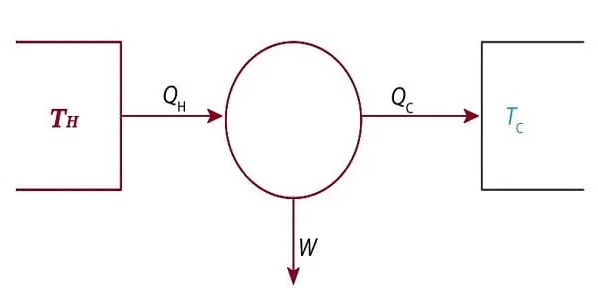
Carnot argued that the body of a liquid could be a constant gas, mercury vapor, alcohol vapor, water vapor, or any substance that can expand, such as air. Engine designs varied in the early days, but typically a boiler (water boiled as it passed through a furnace) was used to supply heat (QH) and a condenser was used to supply QC.
The output work W represents the movement of the piston. A piston was used to drive the pulley. However, it is used to rotate the crank.
Parts of Carnot engine
- Source
- Sink
- Cylinder
- Insulating Stand
- Piston
Limitations
- This is a ideal cycle. That is, the Carnot cycle does not exist and cannot be configured. Therefore, the Carnot cycle is only a theoretical concept.
- According to thermodynamics, temperature does not change in an isothermal process, and the Carnot cycle indicates that heat is supplied in an isothermal expansion process. This is impossible.
- The Carnot cycle describes only the heat engine and not other types of equipment. Heat loss can occur in a real engine, but the Carnot cycle is the other way around.