Table of Contents
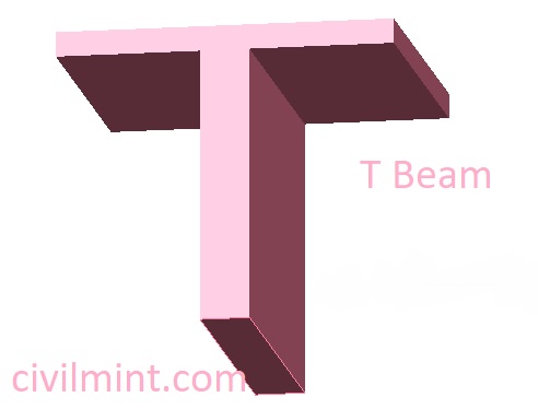
What Is T Beam?
It’s just a rectangular beam cast monolithically with the slab-shaped as T.
T-beams possess a low volume of concrete. Additionally, they lessen the floor-to-floor height since the flange is already part of the slab. These two things in combination significantly decrease the concrete needed for the building, cutting down both cost and dead load on the structure.
This type of beam has a greater second moment of inertia as compared to the conventional rectangular beams, so they have a greater capacity to resist bending effectively.
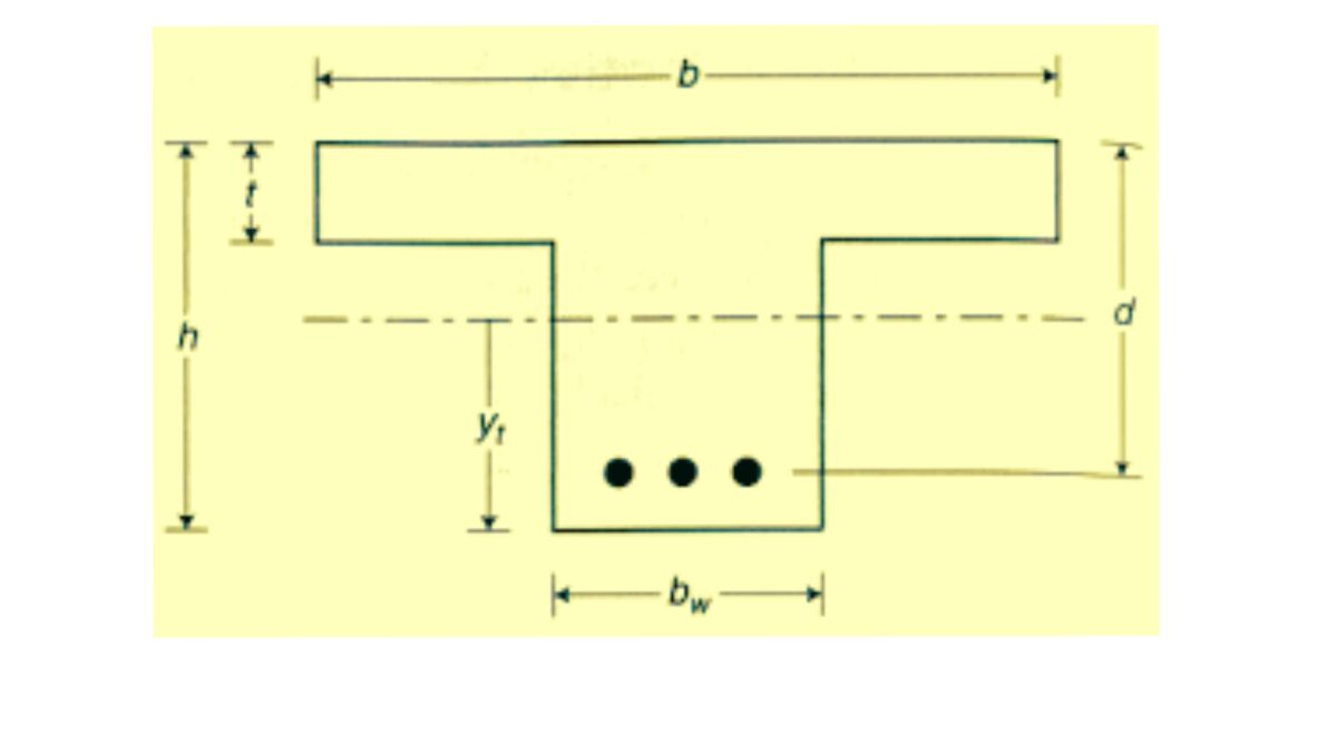
Mass divided in the T-beam is consist of Flanges and web. Flanges are more viable in resisting bending stresses while the Web is more resistive in shear stresses.
Types Of T Beam
T beams can be classified on the basis of their geometry. I have described 5 types of T beam.
1. Symmetrical T-beam:
This type of T-beam has a symmetrical cross-section, with the flanges and web having the same dimensions. The load is evenly distributed between the flanges and the web.
2. Inverted T-beam:
In an inverted T-beam, the flange is placed at the bottom, while the web is at the top. This type of T-beam is commonly used in bridge construction.
3. Asymmetrical T-beam:
An asymmetrical T-beam has a non-uniform cross-section, with the flanges and web having different dimensions. This type of T-beam is used in situations where the load is not evenly distributed.
4. Slimflor beam:
This is a type of T-beam that has a reduced concrete slab thickness. It is designed to be used in situations where headroom is limited, such as in basement car parks or high-rise buildings.
5. Tapered T-beam:
This type of T-beam has a cross-section that tapers from one end to the other. It is commonly used in bridge construction, where the load is heaviest at one end.
Moment Of Inertia Of T Beam
Watch the video to know how to calculate moment of inertia of T beam.
T Beam Design
The design of a T-beam involves calculating the section dimensions and reinforcement required to resist the maximum moment and shear force that the beam will experience. The following steps can be used to design a T-beam:
Step 1: Determine the loads and span
The first step is to determine the loads that the beam will be subjected to, including dead loads, live loads, and other loads like wind or earthquake. Also, determine the span of the beam, which is the distance between its supports.
Let’s assume the following data for a T-beam design:
- Dead load = 10 kN/m
- Live load = 20 kN/m
- Span = 6 m
Step 2: Calculate the moment and shear force
Based on the loads and span, calculate the maximum moment and shear force that the beam will experience. Moment is the bending force that causes the beam to bend, while shear force is the force that acts perpendicular to the axis of the beam.
The maximum moment and shear force can be calculated using the following formulas:
Maximum moment = (dead load + live load) x span^2 / 8
Maximum shear force = (dead load + live load) x span / 2
For our example, the maximum moment and shear force can be calculated as follows:
Maximum moment = (10 + 20) x 6^2 / 8 = 135 kN-m Maximum shear force = (10 + 20) x 6 / 2 = 45 kN
Step 3: Choose the section dimensions
Based on the moment and shear force, choose the dimensions of the T-beam section. The depth of the stem is usually determined based on the span of the beam, while the width of the flange is determined based on the loads and the moment. The thickness of the stem and flange is usually taken as a standard value.
Let’s assume the following dimensions for the T-beam section:
- Overall depth of the beam = 600 mm
- Width of the flange = 200 mm
- Thickness of the stem = 100 mm
- Thickness of the flange = 50 mm
Step 4: Determine the reinforcement
Based on the section dimensions and the moment, determine the amount and placement of reinforcement. This is usually done using the principles of reinforced concrete design, which involves calculating the required area of steel reinforcement based on the bending moment and the tensile strength of the concrete.
The reinforcement required for the T-beam can be calculated using the following formulas:
Area of steel reinforcement required = maximum moment / (0.87 x fy x d)
Effective depth = overall depth – 0.5 x thickness of the flange – 0.5 x diameter of reinforcement
Spacing of reinforcement = effective depth / number of bars
where:
fy = yield strength of steel reinforcement d = effective depth of the beam
Let’s assume the following properties for the steel reinforcement and concrete:
- Yield strength of steel reinforcement (fy) = 415 MPa
- Tensile strength of concrete (ft) = 3 MPa
- Diameter of reinforcement = 16 mm
Using these values, the area of steel reinforcement required can be calculated as follows:
Area of steel reinforcement required = 135 x 10^6 / (0.87 x 415 x (600 – 50 – 16/2)) = 754.7 mm^2
Assuming that we use 4 bars of 16 mm diameter, the spacing of reinforcement can be calculated as follows:
Effective depth = 600 – 0.5 x 50 – 0.5 x 16 = 567 mm
Spacing of reinforcement = 567 mm / 4 = 141.75 mm (say 140 mm)
Therefore, the T-beam design requires 4 bars of 16 mm diameter, spaced at 140 mm center-to-center, placed at the bottom of the beam.
Step 5: Check for deflection and cracking
After designing the T-beam for strength, it is important to check for deflection and cracking. The deflection can be checked using the allowable deflection limit, which is usually specified by the building code or standards. The cracking can be checked using the maximum allowable crack width, which is also specified by the building code or standards.
If the T-beam design does not meet the deflection and cracking limits, the section dimensions or reinforcement can be adjusted accordingly.
The design of a T-beam involves calculating the section dimensions and reinforcement required to resist the maximum moment and shear force that the beam will experience. The design process involves calculating the loads and span, determining the moment and shear force, choosing the section dimensions, determining the reinforcement, and checking for deflection and cracking. The design process can be performed using numerical formulas and the principles of reinforced concrete design.
Advantages Of T Beam:
- Since the beam is cast monolithically with the slab, the flange also takes up the compressive stresses which means, it will be much more effective in resisting the sagging moment acting on the beam.
- Better headroom is the direct outcome of the first point since the depth of the beam can be considerably decreased.
- For larger spans, T beams are normally preferred rather than rectangular beams as the deflection is decreased to a good extent.
Disadvantages of T Beam:
- There is a considerable increment in the shear stress at the junction of the flange and the web of the beam due to the change in cross-section. Hence casting should be done very carefully to assure both are bonded well.
- Since the beam slab is monolithic (rigid), it becomes very feeble in resisting lateral shear forces. (cracks develops quickly). Thus usually in earthquake-prone zones using T beams for high-rise buildings is reinforced with mechanical stiffeners in the junction.
- There will be little savings in steel too (not a significant amount though).