California Bearing Ratio test or CBR is used to calculate the strength of the material for pavement design. CBR test is the test that was developed by the California state highway department of the USA for the determination of subgrade strength of highway and air-filled pavement.
It is a penetration test. In this test, a standard piston is utilized to penetrate the soil at a standard rate of 1.25 mm/minute. CBR value is determined as the ratio of load per unit area needed to penetrate a soil mass by a standard plunger at a specified rate to that corresponding load needed to penetrate standard material. Here standard material is one having a CBR estimation of 100%. CBR esteem is generally decided at 2.5mm or 5mm penetration.
Table of Contents
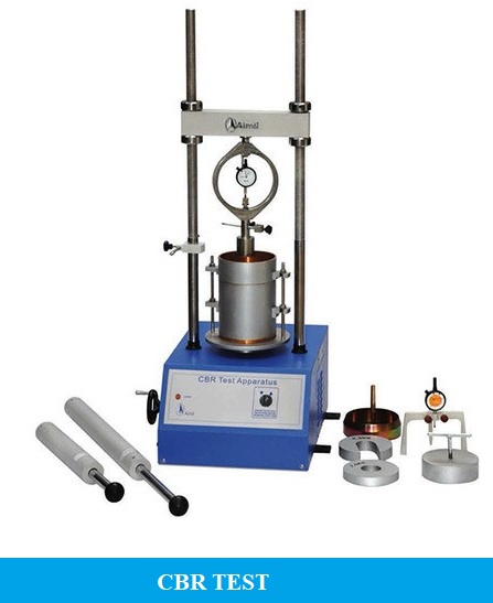
CBR Test Apparatus:
- A mould that has an internal diameter of 150 mm and 175 mm.
- A detachable collar and the detachable base plate having perforations at the bottom.
- A space disc.
- The central hole of 53 mm in diameter.
- A loading machine having a capacity of 5000 kg.
- Proving ring.
- Compaction rammers.
- Dial gauges.
- Filter papers.
- Weight balance.
- Mixing tool
- Tray
- Measuring cylinder.
CBR Test Procedure:
CBR test completed in two steps as follows:
- Preparation Of Test Specimen.
- Procedure For Penetration Test.
1. Preparation Of Test Specimen:
- The material utilized in the remoulded specimen should pass 19 millimeters IS Sieve. Allowance for larger material should be made by replacing it with an equal amount of material that passes a 19-millimeters IS Sieve but is retained on 4.75-millimeters IS Sieve.
- The dry density for a remoulding shall be either the field density or the value of the maximum dry density estimated by the compaction test. The water content utilized for compaction shall be the optimum water content.
- A representative sample of the soil weighing approximately 4.5 kilograms or more for fine-grained soil and 5.5 kilograms or more for granular soil shall be taken and mixed thoroughly with water. If the soil is to be compacted to the maximum dry density at the optimum moisture content, the exact mass of the soil needed shall be taken and the necessary quantity of water added so that the water content of the soil sample is equal to the calculated optimum moisture content.
- Set the extension collar and the base plate to the mould. thereafter, Insert the spacer disc over the base. Fix the filter paper on the top of the spacer disc.
- Apply Lubricating Oil to the inner side of the mould. Compact the mixed soil in the mould using heavy compaction. i.e. compact the soil in 5 layers with 55 blows to each layer by the 4.89 kilograms rammer.
- Remove the extension collar and trim the compacted soil carefully at the level of the top of mould, by means of a straight edge. Any holes created on the surface of the compacted soil by removal of the coarse material shall be patched with the smaller size material. Remove the perforated base plate, Spacer disc, and filter paper and record the mass of the mould and compacted soil specimen. Place a disc of coarse filter paper on the perforated base plate, invert the mould and compacted soil, and clamp the perforated base plate to the mould with the compacted soil in contact with the filter paper.
- Place a filter paper over the specimen and place the perforated plate on the compacted soil specimen in the mould. Put annular weights to generate a surcharge similar to the weight of base material and pavement, to the nearest 2.5 kilograms.
- Immerse the mould assembly and weights in a tank of water and soak it for 96 hours. Mount the tripod for expansion measuring device on the edge of the mould and record initial dial gauge reading. Note down the readings every day against the time of reading. A constant water level shall be maintained in the tank throughout the period.
- At the end of the soaking period, note down the final reading of the dial gauge and take the mould out of the water tank.
- Remove the perforated plate and the top filter paper. Weigh the soaked soil sample and record the weight.
2. Procedure For Penetration Test
- Place the mould assembly with the test specimen on the lower plate of the penetration testing machine. To stop upheaval of soil into the hole of the surcharge weights, 2.5-kilogram annular weight shall be placed on the soil surface before seating the penetration plunger after which the remainder of the surcharge weights shall be placed.
- Seat the penetration piston at the center of the specimen with the smallest possible load, but in no case in excess of 4 kilograms so that full contact of the piston on the sample is established.
- Set the load and deformation gauges to read zero. Apply the load on the piston so that the penetration rate is about 1.25 millimeters/minute.
- Record the load readings at penetrations of 0.5, 1.0, 1.5, 2.0, 2.5, 4.0, 5.0, 7.5, 10 and 12.5 millimeters.
- Raise the plunger and detach the mould from the loading equipment. Take about 20 to 50 grams of soil from the top 30 millimeters layer and determine the moisture content.
Observation And Recording
| Penetration(millimeters) | Applied Load (kilogram) |
|---|---|
| 0.50 | |
| 1.00 | |
| 1.50 | |
| 2.00 | |
| 2.50 | |
| 4.00 | |
| 5.00 | |
| 7.50 | |
| 10.00 | |
| 12.50 |
Calculation
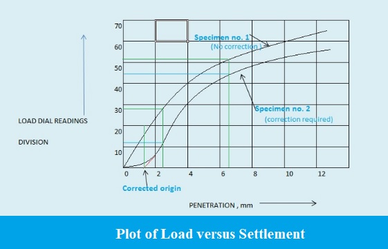
- If the initial part of the curve is concave upwards, apply correction by drawing a tangent to the curve at the point of the highest slope and shift the origin. Find and record the correct load reading corresponding to each penetration.
C.B.R. = (PT/PS) X 100 where PT = Corrected test load corresponding to the chosen penetration from the load penetration curve.
PS = Standard load for the same penetration taken from the table above. - C.B.R. of the specimen at 2.5 millimeters penetration =
- C.B.R. of the specimen at 5.0 millimeters penetration =
- The C.B.R. values are generally determined for penetration of 2.5 millimeters and 5 millimeters. Normally, the C.B.R. value at 2.5 millimeters will be greater than at 5 millimeters and in such a case the former shall be taken as C.B.R. for design purpose. If C.B.R. for 5 millimeters exceeds that for 2.5 millimeters, the test should be repeated. If identical results follow, the C.B.R. corresponding to 5 millimeters penetration should be taken for design.
Graph
Draw a chart between Load versus Penetration.